VHDL TutorialVHDL tutorial provides basic and advanced concepts of VHDL. Our VHDL tutorial is designed for beginners and professionals.
What is HDL?HDL stands for Hardware Description Language. It is a programming language that is used to describe, simulate, and create hardware like digital circuits (ICS). HDL is mainly used to discover the faults in the design before implementing it in the hardware. The main advantage of HDLs is that it provides flexible modeling capabilities and can express the large complex designs (>107 gates). Today, there are many HDLs available in the market, but VHDL and Verilog are the most popular HDLs. What is VHDL?VHDL stands for Very High-Speed Integration Circuit HDL (Hardware Description Language). It is an IEEE (Institute of Electrical and Electronics Engineers) standard hardware description language that is used to describe and simulate the behavior of complex digital circuits. The most popular examples of VHDL are Odd Parity Generator, Pulse Generator, Priority Encoder, Behavioral Model for 16 words, 8bit RAM, etc. VHDL supports the following features:
What is Verilog?Verilog is also a HDL (Hardware Description Languages) for describing electronic circuits and systems. It is used in both hardware simulation and synthesis. The most popular examples of Verilog are network switch, a microprocessor, a memory, a simple flip-flop, etc. Difference between VHDL and Verilog
History of VHDLVHDL was developed by the Department of Defence (DOD) in 1980.
Why VHDL?VHDL is used for the following purposes:
Advantages of VHDLA list of advantages of VHDL is given below:
Disadvantages of VHDLA list of disadvantages of VHDL is given below:
Basic Elements of VHDLThere are the following three basic elements of VHDL: 1. EntityThe Entity is used to specify the input and output ports of the circuit. An Entity usually has one or more ports that can be inputs (in), outputs (out), input-outputs (inout), or buffer. An Entity may also include a set of generic values that are used to declare properties of the circuit. Entity Declaration You can declare an entity using the following syntax:
Example:
If an entity is generic, then it must be declared before the ports. Generic does not have a mode, so it can only pass information into the entity. Syntax: Example: Rules for writing Port name: - Port name consist of letters, digits, and underscores. Modes of Port in Input port 2. ArchitectureArchitecture is the actual description of the design, which is used to describe how the circuit operates. It can contain both concurrent and sequential statements. Architecture Declaration An architecture can be declared using the following syntax: Example: 3. ConfigurationA configuration defines how the design hierarchy is linked together. It is also used to associate architecture with an entity. Configuration Declaration Example: Types of Modeling styles in VHDLThere are 4 types of modeling styles in VHDL: 1. Data flow modeling (Design Equations) Data flow modeling can be described based on the Boolean expression. It shows how the data flows from input to output. It works on Concurrent execution. 2. Behavioral modeling (Explains Behaviour) Behavioral modeling is used to execute statements sequentially. It shows that how the system performs according to the current statement. Behavioral modeling may contain Process statements, Sequential statements, Signal assignment statements, and wait statements. 3. Structural modeling (Connection of sub modules) Structural modeling is used to specify the functionality and structure of the circuit. Structural modeling contain signal declarations, component instances, and port maps in component instance. VHDL objectsVHDL uses the following three types of objects: 1. Constants Constant is an object which can only hold a single value that cannot be changed during the whole code. Example: constant number_of_bytes integer:=8; 2. Variables A variable also holds a single value of a given type. The value of the variable may be changed during the simulation by using variable assignment operator. Variables are used in the processes and subprograms. Variables are assigned by the assignment operator ":=". Example: variable index: integer :=0; 3. Signals Signals can be declared in architecture and used anywhere within the architecture. Signals are assigned by the assignment operator "<=". Example: Signal sig1: std_logic; Data Types in VHDLData Types are the abstract representation of stored data. There are the following data types in VHDL - 1. Scalar Types
2. Composite Types
VHDL OperatorsVHDL Operators are used for constructing the expressions. There are the following types of operators in VHDL: 1. Logical Operators Logical Operators are used to control the program flow. When the logical operators combined with signals or variables, then it is used to create combinational logic. VHDL supports the following logical operators:
2. Relational Operators In VHDL, relational operators are used to compare two operands of the same data type, and the received result is always of the Boolean type. VHDL supports the following Relational Operators:
3. Arithmetic Operators Arithmetic Operators are used to perform arithmetic operations. These operators are numeric types, such as integer and real. VHDL uses the following Arithmetic Operators:
4. Shift Operators In VHDL, shift operator is used to perform the bit manipulation on the data by shifting and rotating the bits of its first operand right or left. VHDL supports the following Miscellaneous Operators:
Note: Operators are evaluated in order to their precedence. (i.e., highest to lowest)
The Operator of equal precedence is evaluated from left to right. Install the Xilinx ISE ToolThere are the following steps to install the Xilinx ISE Tool - Step1: Click on the below link to download the Xilinx ISE tool. Step2: Now go to ISE Design suite - 14.7 Full Product Installation and select Full Installer for Windows 7/XP server (TAR/GRIP - 6.18 GB) as shown in the below screenshot. 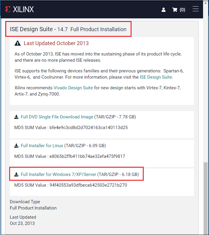
Step 3: Once you click on the "Full Installer for windows 7/XP/Server", you will see that a Xilinx sign in page appears. If you do not have an account of Xilinx, then click on the Create your account. 
Step 4: Fill the information in the registration page then click on the Create Account. 
Step 5: After clicking on the Create Account, the following window appears. 
Step 6: Now, you will receive a mail on your registered e-mail id which contains an activation link. Click on the link to activate your account. Step 7: Once you click on the link, a sign in to activate account window appears in the window, in which enter your Username and Password, then click on the Sign In. 
Step 8: Now click on the below link for the Name and Address Verification. https://www.xilinx.com/member/forms/download/xef.html?filename=Xilinx_ISE_DS_Win_14.7_1015_1.tar Step 9: After completing the verification form, click on the Next. 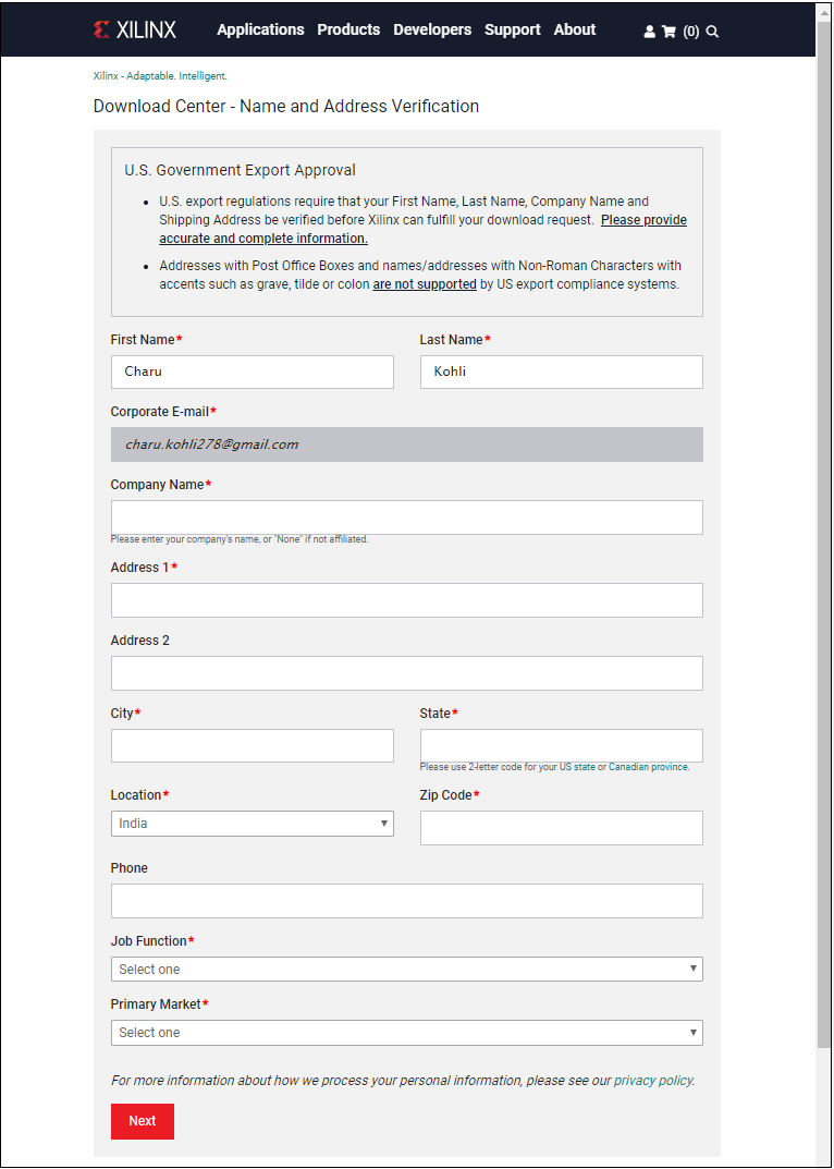
Step 10: Now, you can see that the Xilinx_ISE tar file is started to download. 
Step 11: Double click on the downloaded file and extract the file to run xsetup.exe. Step 12: Once you run the Application, the following Welcome window appears on the screen. 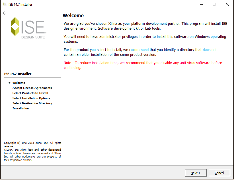
Step 13: Tick on the I accept and agree to the terms and conditions above and also tick on the I also accept and agree to the following terms and conditions then click on the Next. 

Step 14: Now, select the listed product to install. For VHDL, select the ISE WebPACK, which is the free version of the software. After selecting the ISE WebPACK, click on the Next. 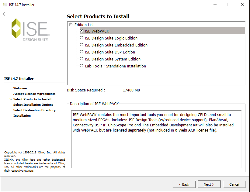
Step 15: The Installation options window appears. In this window, click on Next. 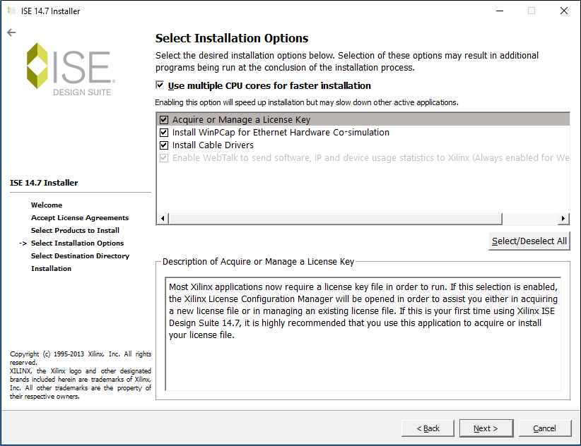
Step 16: Select the Destination Directory, then click on the Next. 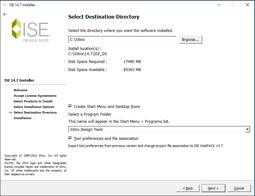
Step 17: You can see the summary of the Installation in the below screenshot. Click on the Install to install the Xilinx. 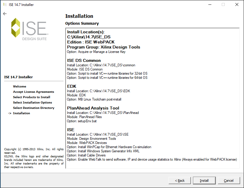
Step 18: You can see that installation is in progress. 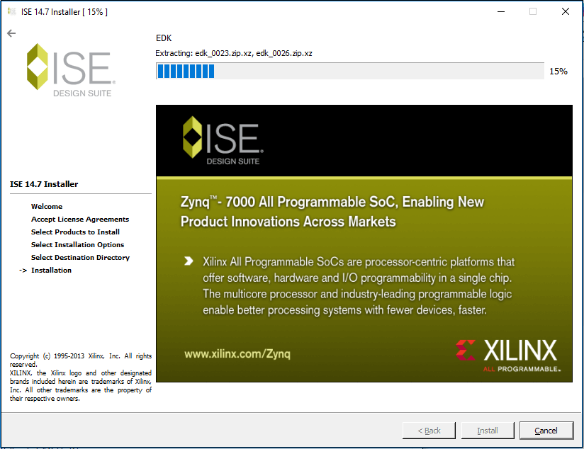
Step 19: Once the installation is completed, click on the Finish. 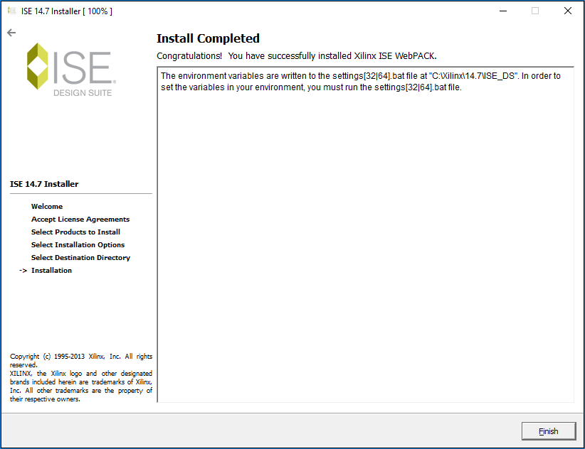
Step 20: Fixing Project Navigator, iMPACT, and License Manager There are the following steps to Fixing Project Navigator, iMPACT, and Licence Manager.
After completing the above steps, you can close the directory. Step 21: Now, you can see IDE Design Suite appears on the screen. Double click on the IDE Design Suite, you can see the following pop up: 
Step 22: Now, the following window appears with a pop-up, click on the OK in the pop-up window. 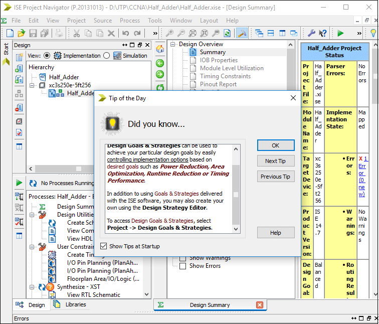
Step 23: When you click on the Licence, the following window will open in which select Get My Purchased Licence (s) then click on the Next. 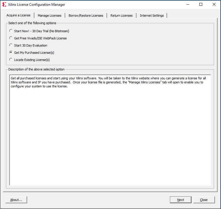
Step 24: To connect with the default browser, click on the Connect Now. 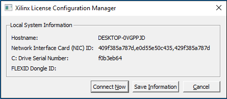
Step 25: It opens a new XILINX page in the browse. On this page, enter Username and password then click on the Sign in. 
Step 26: After clicking on the Sign In, the following window appears. 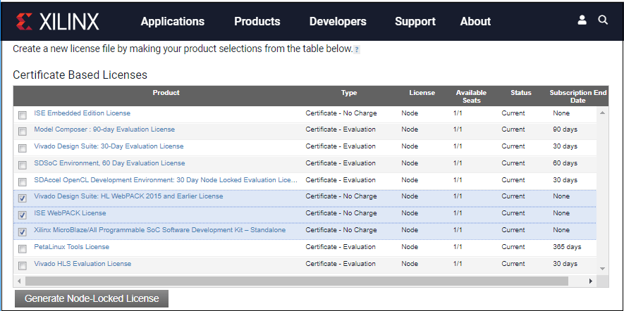
Step 27: Once you select the file, an e-mail is received in your registered e-mail id, which consists of a Xilinx.lic file. You need to download this file. Click on the load Licence to upload the downloaded license file then click on the close. 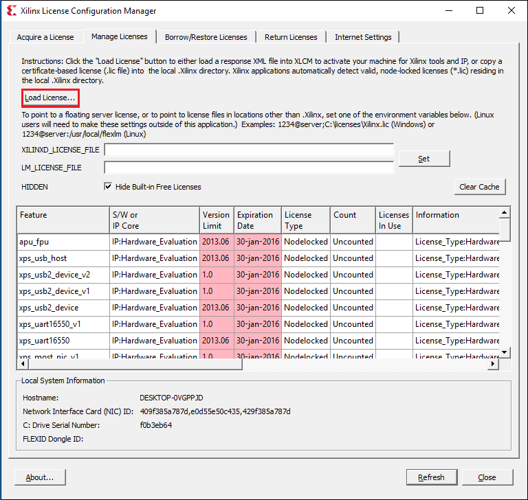
Step 28: Once the file is uploaded, a pop occurs with the message Licence installation was successful, click on the OK in the pop-up and then click on the close. The below screenshot shows the licence is uploaded. 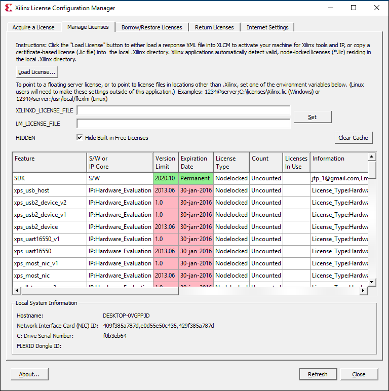
Step 29: Now, you can create the projects in the Xilinx tool. 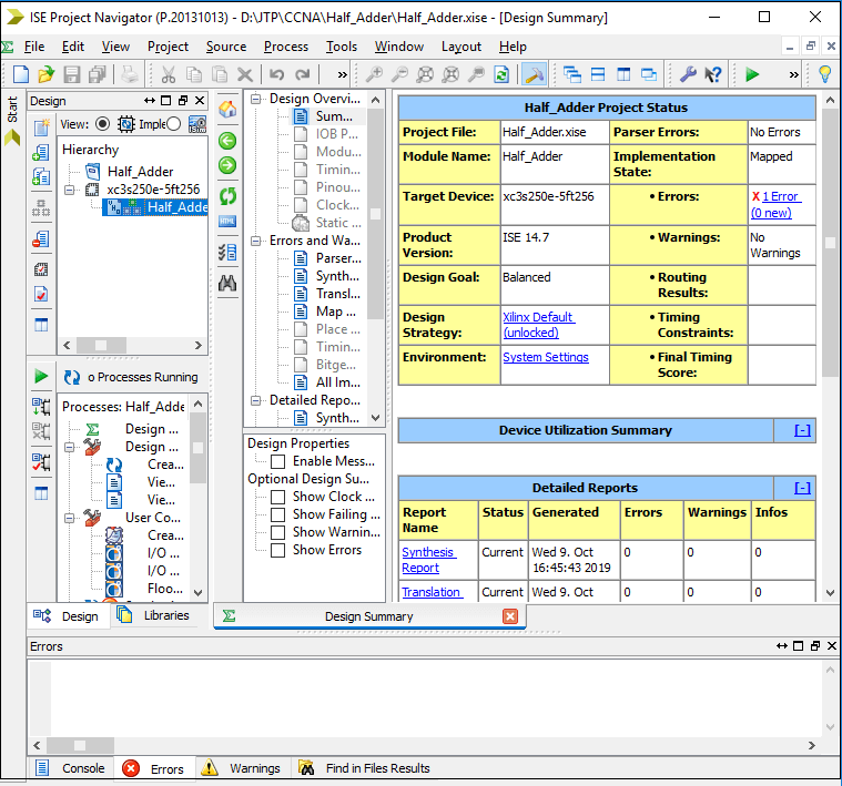
Creating a project in VHDL using Xilinx IDE ToolThere are the following steps for creating a project in Xilinx - Step1: Creating a new project To create the new project, Select File -> New Project. It will open a new project window on the desktop. 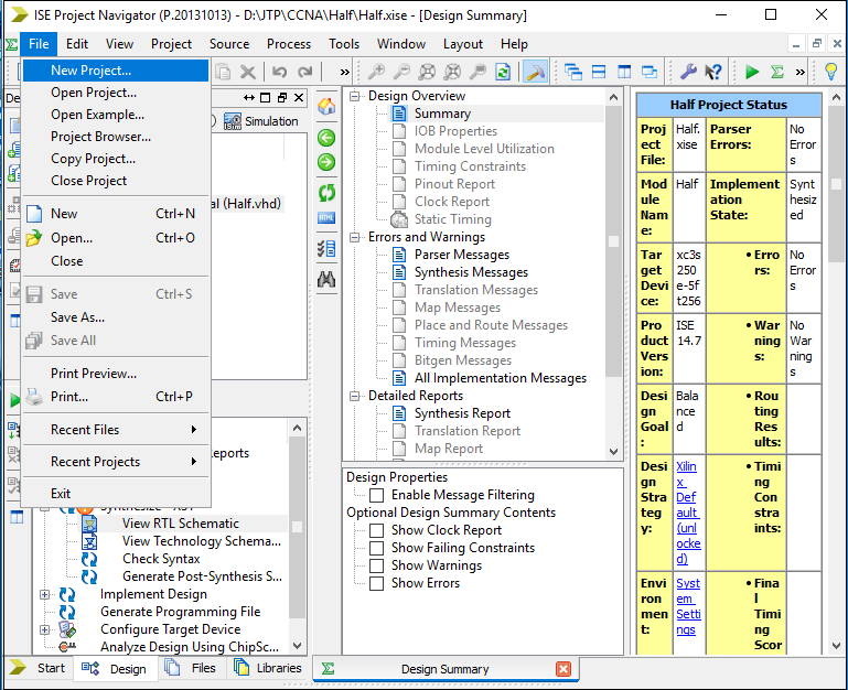
In the new project window, give the Project Name that you want to create and specify the location (directory path) where you want to save the project, then click on the Next. 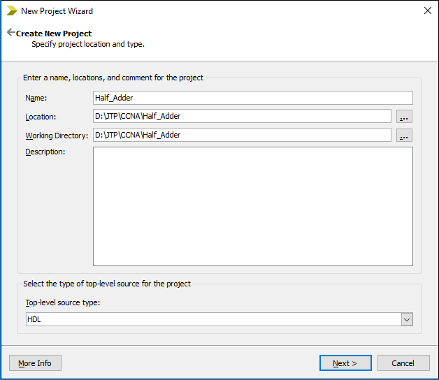
Note: Make sure that Top-level source type is selected as the HDL, rather than Schematic, EDIF, or other stuff.After clicking on the Next button, the following window appears, which shows the project properties. Fill the properties according to your requirements then click on the Next. 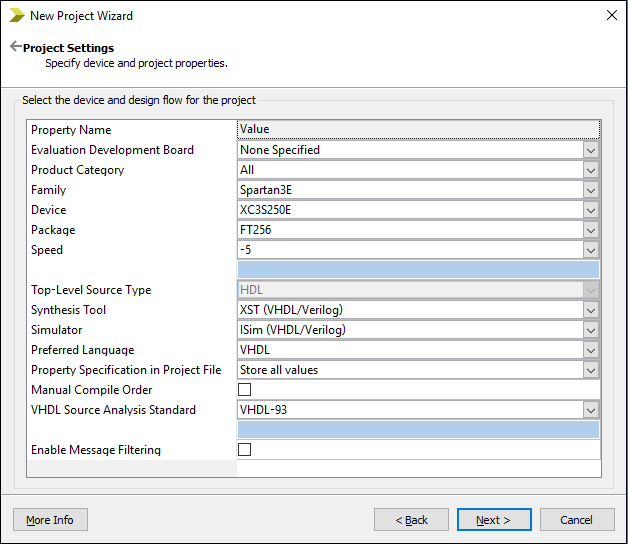
After clicking on the Next button, the following window appears, which shows the Project Summary. If the project summary matches with your requirement, then click on the Finish. Otherwise, click on the Back and fill property according to your requirement. 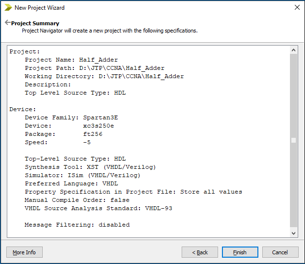
Step2: Create VHDL Source To add the VHDL source in VHDL, click on New Source in the project Wizard, or click on the Project ->New Source. 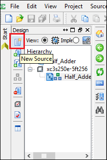
Type your file name, specify the location, and select VHDL Module as the source type. Make sure that the Add to Project check box is selected, then click on the Next. 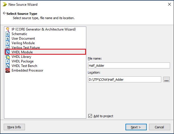
Step 3: Assign the ports for VHDL source To design the Half Adder, you can assign a port name as a, b, sum, and cout. Where for a and b are treated as the input ports, so select in from the drop-down menu. sum and cout are treated as the output ports, so select out from the drop-down menu. 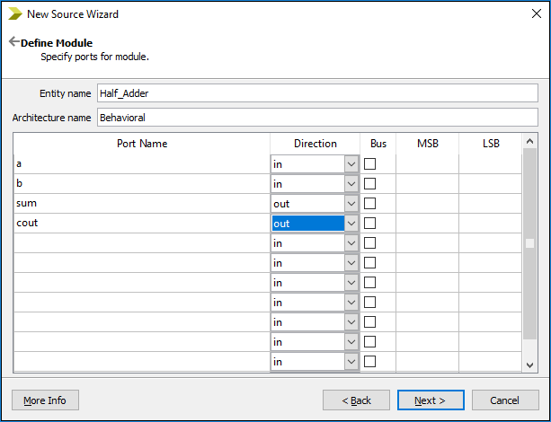
The following screenshot shows a summary of the project. 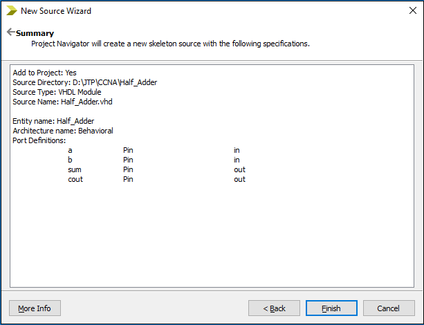
Step 4: Enter and edit VHDL code The following screenshot shows the automatically generated Half_Adder code. 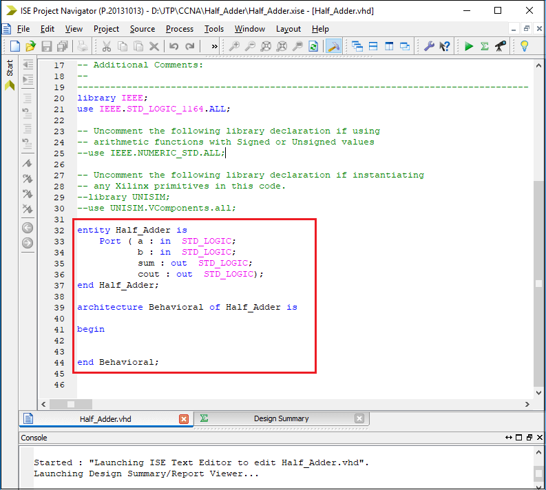
To design the Half_Adder, enter the following code in the working area. 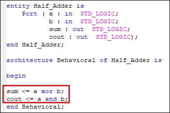
Step 5: Synthesize the Code When your source file is completed, you need to check the syntax of the design. To check the syntax, Click on the Synthesize-XST process to expand the hierarchy. Now, double click on the Check syntax. You can see that an ISE compilation process is started. If the ISE process completed successfully, a green checkmark appears. Otherwise, a red X appears which show that there were errors and process failed. 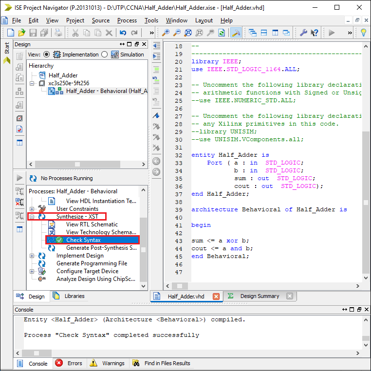
To see the basic design of half adder double click on the View RTL Schematic. 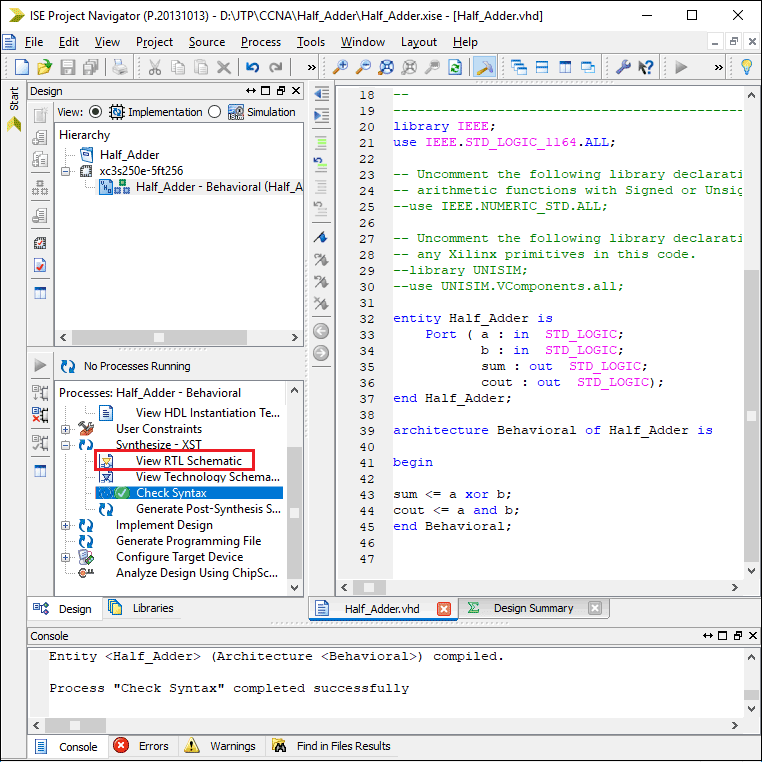
Now you will see the following pop up in which click on the OK. 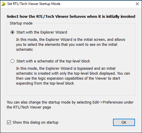
In the create RTL Schematic, select the project from the Available list, and then click on the Add button to move the selected project to the Selected Elements and click on the Create Schematic. 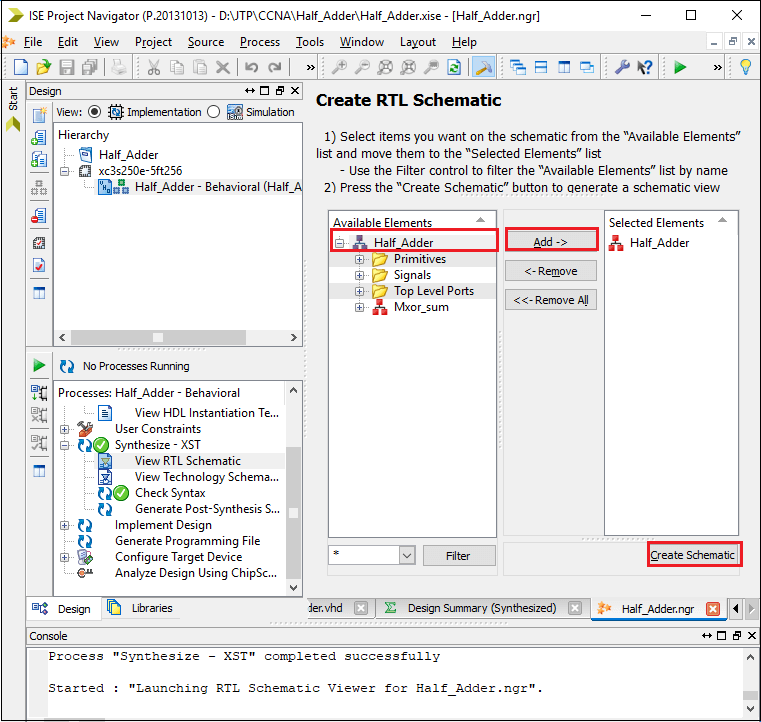
Now, you can see the external design of half Adder on the screen. 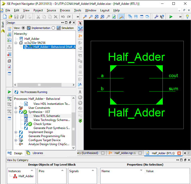
When you double click on the above rectangle, you can see the internal diagram using the logical gates. 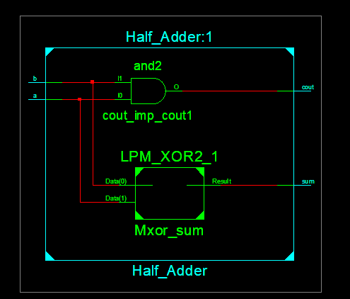
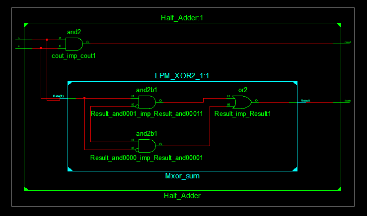
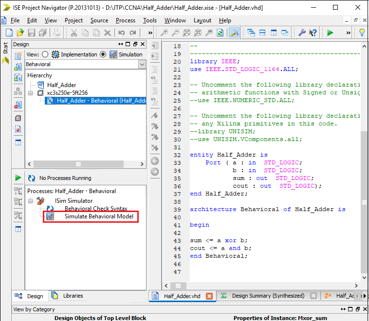
Step 6: Simulating Behavioral Model (ISE Simulator) To check the behavioral model, select the Implementation-> Half_Adder- Behavioral (Half_Adder.vhd) and double click on the Simulate Behavioral Model.
If the simulation is successful, the following window opens. 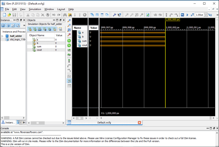
To assign the value, right-click on the given values(U) then select Force Constant. Consider the below image: 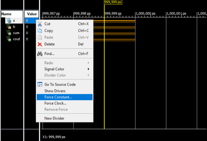
The following pop up will occur in which you can assign the value of a, then click on the Apply and OK. 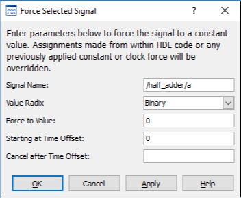
Case 1: If input is: a = 0 Output: sum = 0 
Case2: If input is - a = 0 Output: sum = 1 
Case 3: Input is - a = 1 Output: sum = 1 
Case 4: Input is - a = 1 Output: sum = 0 
VHDL vs. C Language
PrerequisiteBefore learning VHDL, you must have the basic knowledge of electronic circuits. AudienceOur VHDL tutorial is designed to help beginners and professionals. ProblemWe assure you that will not find any problem in this VHDL tutorial. But if there is any mistake or error, please post the error in the contact form. |
 For Videos Join Our Youtube Channel: Join Now
Feedback
- Send your Feedback to [email protected]
Help Others, Please Share


