| |

What is the full form of PCMPCM: Pulse Code ModulationPCM Stands for Pulse Code Modulation. When a carrier signal's characteristics are changed in response to the message signal's current values, this process is known as modulation. The carrier signal, which has a high frequency and carries no data but is used for long-distance transmission, is the signal that is being conveyed for communication. The message signal is the signal that is being transmitted for communication. Numerous modulation methods exist, and they are divided into groups based on the kind of modulation they use. Pulse Code Modulation is the one that is most frequently used for digital modulation. To transform a signal's analogue information into a binary sequence, or 1s and 0s, pulse code modulation is used. A binary sequence will appear in a PCM's output. PCM generates a string of digits, which is why this method is referred to as digital. Despite being expressed in binary code, each of these digits corresponds to the approx amplitude of the signal sample at that precise moment. The message signal is represented by a series of coded pulses in pulse code modulation. This message signal is produced by discretizing the signal's amplitude and temporal components. To generate a string of binary numbers or digits, pulse code modulation techniques are used. Thus, the name "digital modulation" is defined for this procedure. The binary codes represent the amplitude of the signal sample at that specific time. The message signal in the PCM process is indicated by a series of coded pulses. The amplitude and time of this message signal are represented. 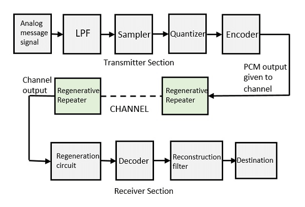
There are two types of pulse code modulations:
All types of analogue data, such as music, telemetry, voice, and full-motion video, can be converted to digital format using the PCM process. The method of quantisation is used to create a pulse code modulated waveform from an analogue waveform at the transmitter end and transform the message signal into binary form. The signal is demodulated and transformed into pulses with the same quantum levels at the receiver end of the pulse code circuit. Basic Elements Of Pulse Code Modulation (PCM)Sampling, Quantizing, and Encoding are done in the analogue-to-digital converter part and make up the transmitter component of a pulse code modulator circuit. Prior to sampling, a low pass filter prevents the aliasing of the message signal. Regeneration of damaged signals, decoding, and reconstruction of the quantized pulse train are the fundamental processes of the receiver section. 1. Low Pass Filter To prevent aliasing of the message signal, this filter removes high-frequency components from the input analogue signal that is higher in frequency than the highest frequency of the message signal. 2. Sampler This method aids in gathering sample data at instantaneous message signal values in order to recreate the original signal. The sampling theorem states that the sample rate must be more than twice the highest frequency component W of the message signal. 3. Quantizer Quantizing is the process of constructing the data and removing extraneous bits. When the sampled output is sent into the Quantizer, the unnecessary bits are removed and the value is compressed. 4. Encoder The encoder converts analogue signals to digital format. Each quantization level is identified by a binary code. Here, sampling was carried out using the sample-and-hold method. The LPF, Sampler, and Quantizer components will function as an analogue to digital converter. Encoding reduces the amount of bandwidth consumed. 5. Regenerative Repeater The signal intensity is increased in this section. To make up for the signal loss, reconstruct the signal, and boost its strength, the channel's output additionally incorporates a regenerative repeater circuit. 6. Decoder For the purpose of recreating the original signal, the decoder circuit decodes the pulse-coded waveform. The demodulator is this circuit. 7. Reconstruction Filter A low-pass filter known as the reconstruction filter is used to recover the original signal following the completion of the digital-to-analogue conversion by the regenerative circuit and the decoder.
Next TopicFull Form
|
 For Videos Join Our Youtube Channel: Join Now
Feedback
- Send your Feedback to [email protected]
Help Others, Please Share


