| |

AC: Alternating CurrentAC or Alternating current is derived from two words, called 'Alternating' and 'current.' The current is the flow of electrons in a substance, material, or object. Alternating signifies repeated changes. Hence, AC is the flow of current that continuously changes its magnitude and direction with time. Let's understand it in detail: AC is generated from power plants located at different locations all over the world. The power plants can be hydroelectric power plants, car alternators, etc. Alternating current starts from zero, reaches the maximum positive value and again drops to zero. Again it starts and reaches the maximum negative value and again drops to zero. It is defined as the first cycle. Similarly, it completes other cycles. Here, we will discuss the following topics: Transmission line and power supply History
AC WaveformThe sinusoidal waveform is the most familiar type of AC waveform. Oscilloscope, also known as CRO (Cathode-Ray Oscilloscope), is a device that displays waveforms. It is often known for the visual representation of voltage signals. The display signal is plotted in the form of a graph. It depicts the changes in a signal over time. The sinusoidal AC waveform is shown below: 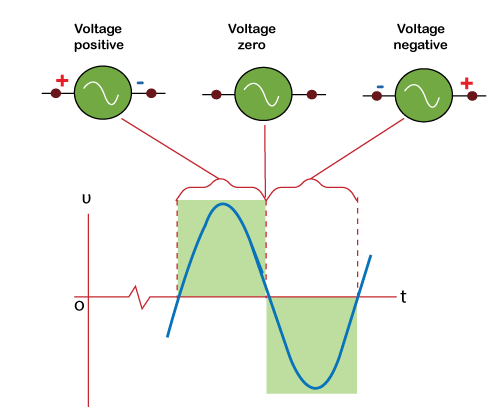
The first half of the signal is the positive part of the sinusoidal wave. It depicts the positive direction of the current. Similarly, the other half is the negative part of the wave and depicts the current's negative direction. AC frequenciesThe frequency of AC can be categorized as low, medium, and high frequency. The frequency above 60Hz is called high frequency. The most common frequencies at which electric power is generated are either 50Hz or 60Hz. Low frequency is also used in different applications because it minimizes the impedance losses. But, low frequency causes the incandescent bulbs to blink. Most of the countries rely on 50Hz frequency applications. During the initial time of the 21st century, hydropower plants generated a frequency of 25Hz. The frequency around 400Hz is used in various applications, such as aircraft, military, submarines, etc. Why is the frequency of 50Hz preferred in most of the countries as compared to 60Hz? Scientists at that time found that the rise in frequency can increase hysteresis and eddy current losses. Hence, 50Hz was preferred for different applications to reduce the current losses. Impact of High FrequenciesThe usual frequency of AC is 60Hz. It is considered as the standard frequency for the operation of AC. 60Hz means sixty cycles per second. Higher frequencies signify a frequency greater than 60Hz. At high frequencies, the impact on Alternating current can be:
Let's discuss the above points in detail. The flow of current is more near the surface of the conductor or wire. It decreases as the depth increases. It means that no current flows around the center of the wire or conductor. The current flows due to the flow of electrons. In a wire or conductor, the acceleration of a charge generates EM radiation waves. Here, the EM wave signifies the electromagnetic field waves. Such EM waves cancel the electricity moving through the center of the conductor or the materials with high conductivity. It is known as the skin effect. Some of the high current-carrying conductors are hollow. It is because of the skin effect. The inner part of a conductor carries little or no current. Creating a hollow conductor saves not only weight but also cost less. Hollow conductors are widely used in transmission lines. It also improves its stability. AC ResistanceAC resistance is generally higher than the Direct Current resistance. DC flows uniformly through the wire or conductor. The Alternating Current is focused more at the surface of a conductor, known as the Skin Effect. It results in the reduction of the cross-sectional area of the conductor. We know that resistance is inversely proportional to the cross-sectional area. The decrease in the cross-sectional area increases the AC resistance. Hence, AC resistance is high as compared to the DC resistance. The increased resistance of AC can also result in high energy losses. In the case of frequencies ranging from low to medium, conductors are generally categorized into a stranded wire arranged in bundles. It allows the alternating current to equally pass through the total area of the stranded conductors. It partially reduces skin effect. The conducting wires arranged in bundles are often known as Litz wire. It is used to transmit current at radio frequencies. The concept based on Litz wire is used in different applications, such as:
Methods to Reduce AC Resistance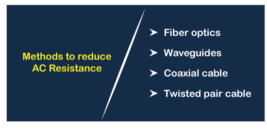
Let's discuss the methods to reduce the resistance of Alternating Current.
Transmission line and power supplyThe device used for energy transfer from one circuit to another is known as a transformer. It can increase or decrease the voltage level. It allows the transmission of AC voltage through the power lines. Power lines are the three-phase based used for transmitting electricity at long distances. It can also transmit high voltages. The wire's efficient resistance helps reduce the heat loss and transmits the Alternating current safer and low voltage for use. Power loss is given as:
P = I^2 R
Where, P is the power loss R is the resistance I is the current in Amperes If the current is reduced to half, the power loss will be reduced to one quarter. It is explained as: I = I/2 P' = (I/2) ^2 R P' = (I/4) R P' = I R / 4 P' = P/4 TransformersA transformer consists of primary and secondary windings. The transformer's primary winding is connected to the Alternating Current power supply, and the secondary winding is delivered the load. The transformer has the ability to step up or down the voltage. The application includes the increase of low AC voltages, a decrease of high AC voltages, etc. 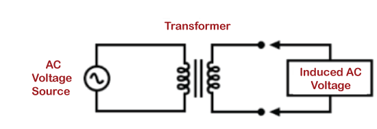
Transformers have become an important aspect of alternating power distribution over recent years. It comes in various designs and sizes. It is an electronic device ranging from small transformers to large transformers used in AC power distribution systems. AlternatorsAlternators are the devices that generate Alternating Current. It is also known as an AC electric generator. Alternators are different from generators in terms of the output voltage. The generator can produce both Alternating and Direct Current, while alternators can only produce alternating current. It can be a linear alternator with a rotating armature and stationary magnetic field. An alternator can also have a rotating magnetic field and stationary Armature. The alternators with rotating magnetic field are considered as the simple alternators with low cost. As compared to the DC motor, the stator in the alternators is not used to provide magnetic flux to the rotor. Instead, a stator in alternators is used to provide grip to the armature winding. Alternators can be single-phase (with one phase) and poly-phase (with multiple phases). The poly-phase alternator also includes a six-phase alternator that is commonly used in large rectifiers. The three-phase alternators are generally used for power generation and transmission. AC MotorsAC motors are defined as electric motors that operate on the applied alternating current. The two main parts of an AC motor are the stator and rotor. A stator is a stationary part of the motor that produces a magnetic field when an electric current is supplied. The rotor is the inside part of the motor. The stator provides a magnetic field to the rotor. The stator can be a permanent magnet or an electromagnet. Let' consider some differences between AC Motor and DC Motor.
There are two types of AC motors called synchronous and asynchronous motors. Among the two motors, the synchronous motor has a high cost and greater efficiency. The rotor's speed and the magnetic field produced by the stator are equal in the synchronous motor. It requires the additional starting torque to make the speed of the rotor equal to the synchronous speed. An asynchronous motor is also known as an induction motor. The speed of the rotor is less and requires no additional starting torque produced by the source. Higher VoltageA voltage above 1KV or 1000V is considered as a high AC voltage. The transmission of power at long distances becomes easy at high voltages. Hence, high voltages are preferred. The transform capability of AC from high to low and vice-versa allows the easy transmission at high-voltages. But, it does not mean that DC cannot move high voltages. There are other advantages of using DC for high voltage transmission. According to the 'I^2 R' loss or Ohm's law, the high voltage transmission is feasible in both AC and DC. Today, for greater efficiency, HVDC is also used for long-distance transmission. Due to cost, voltage conversion, etc., AC is mostly used in high voltage transmission lines. The advantages of transmitting high voltages are:
The disadvantages of transmitting high voltages are listed below:
Power transmitted at higher voltages has less current loss than the same power transmitted at a lower voltage level. The power transmitted in transmission lines is around hundreds of kilovolts. The power is further transferred to low-level lines after converting down into tens of kilovolts. The power is again transformed down for use in households, which is between 100 and 230V. We know that power is transmitted on three-phase transmission lines. Let's discuss the three-phase transmission in detail. We will also discuss the single-phase transmission. Three-phase power generationLet's discuss the three-phase power generation in detail. What is a three-phase system?A three-phase system is widely used to transfer power. It is also used to deliver power to the electric motors. Two-phase system and single-phase systems are also a part of power transmission. The three-phase circuit consists of three alternating current phases that are separated by an angle of 120 degrees. It produces current waveforms that are also separated by an equal distance. The three current waveforms to each other are out of phase at the angle of 120 degrees. The circuits with a higher number of poles are generally preferred. The separation angle can be calculated by dividing 360 with several poles x 3. It is because a pole consists of three phases. A 12 poles machine will include 12x3 = 36. The separation will be 360/36 = 10 degree spacing. In the case of a linear load, the current will be equal among all the phases. There will be no current flowing through the neutral point. If we consider a worst-case linear load, the neutral current will still not exceed the maximum phase current. But, in the case of non-linear load, harmonics can occur. A three-phase system requires less conducting material than the two-phase system and single-phase system to deliver the same amount of power. It has better efficiency, low power loss as compared to the other two phase-systems. Hence, a three-system is generally preferred for commercial use. Why are three-phase systems preferred in electric motors? The electric motors require continuous current for their operation. The three-phase system, with a balanced load, carries an equal amount of current. The produced magnetic field by the three-phase system has a constant magnitude that requires no starting torque. Hence, three-phase systems are generally preferred in electric motors. Is a single-phase system with neutral better than a three-phase system? No. A single-phase system comprises of a phase and a neutral. Simultaneously, a three-phase system has three phases that can transmit the power three times compared to a single-phase. Single-phase systems are mostly used in households. Concept of the fourth wireThree-phase systems often require the use of a fourth wire, i.e., the neutral wire. The neutral wire is also used with the single-phase system and two-phase systems for applications at a small scale. Three-phase systems with neutral wire are used in large installations. The neutral wire ensures the constant supply of voltage to the three phases. The connections are created such that each phase of the power system can deliver equal power. The concept of the fourth wire is also useful in unbalanced loads. The unbalanced or extra current flowing through the circuit gets a path through the fourth wire or neutral wire. It allows the appliances to receive the desired phase voltage. It helps in achieving the required performance. The neutral wire is positioned at the ground level. Hence, any current passing through the neutral wire will not affect the other phase voltage passing through the appliances. Power TransmissionThe power transmission can be overhead and underground. Let's discuss the two types of power transmission techniques in detail. Overhead AC TransmissionOverhead AC transmission signifies the overhead wires suspended by poles for distance transmission. It consists of wire in the form of conductors that carries current from one place to another. These conducting wires are not covered with any type of insulated material. Air is the only insulation material for these types of conducting wires in the overhead transmission. It is in the form of strands made of the commonly used alloy material called aluminum. It is due to the lightweight aluminum. The material and resistance of the conductor depend on the current handling capacity. The material and weight of the less used center part cost more. Hence, multiple strands of conductors in the form of bundles are used at high voltage. It also reduces energy loss. The voltage above 765,000V or 765kV is known as extra-high voltage. The medium voltage used for overhead transmission is around 110,000V or 110kV. The external environmental conditions, such as high winds or high rain, can cause damage the poles or related circuitry. Underground AC TransmissionThe electric power can also be transmitted underground. The underground AC transmission is generally less affected by external weather conditions due to underground cables. But, the cost of an underground cable is higher than the cost of overhead cables. Any leakage or electrical fault can damage the underground pipes. The liquid nitrogen is used to freeze the part of the damaged part. The repairing cost of these pipes is generally high. The AC cables used in underground transmission are limited in length due to their capacitance. It lacks in providing power to the loads beyond 80 kilometers. In the case of DC, the cables are not limited due to the capacitance. It requires HVDC (High Voltage Direct Current) stations to convert the DC power to AC. The HVDC stations are used at both ends of the DC cables for effective transmission. AC Formula
P = VI ………………….. (1)
Where, P is the power The unit of power is Watt. V is the voltage The unit of voltage is Volts I is the current The unit of current is Amperes We know V =IR Putting the value of V in equation number 1, we get:
P = I^2 R ………………….. (2)
We know, I = V/R Putting the value of I in equation number 2, we get:
P = (V/R) ^2 R
P = V^2/ R The AC voltage as a function of time can be represented as: v(t)=Vpsinωt Where, Vp -peak voltage ω - Angular frequency The angular frequency can also be written as: ω=2πf Where, F is the frequency in Hertz AC Power As discussed above,
P = V^2/ R
The AC power can be represented as:
P(t) = v(t)^2/ R
Where, R is the load resistance P(t) is the instantaneous power as the function of time. Let's calculate the average power. Average power can be represented as: 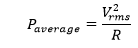
In terms of AC voltage, the current can be represented as: 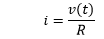
Putting the value,v(t)=Vpsinωt, we get: 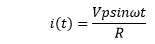
The power can be represented as: P(t) = v(t)i(t) Putting the value of i(t) in the above equation, we get: 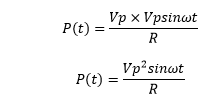
RMS voltage for the sinusoidal wave can be represented as: 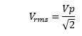
RMS voltage for the triangular wave can be represented as: 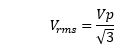
RMS voltage for the square wave can be represented as: 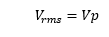
AC Phasor diagramLet's consider the phasor diagram of the sinusoidal wave. 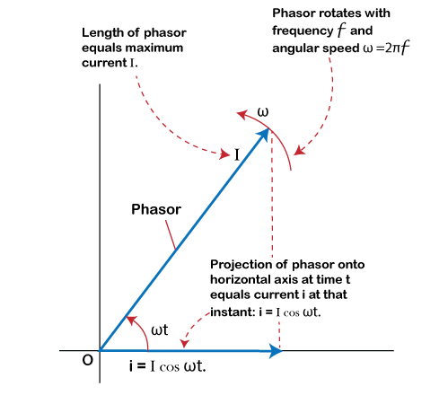
Phasor is defined as the vector that rotates in the anticlockwise direction with the constant frequency w. The AC voltage is represented as: V=Vocosωt The Alternating current is represented as: I=Iocosωt As discussed above, V = IR Putting the value of Alternating current (I) in the above equation, we get: V=Iocosωt×R Where, Vr is the instantaneous potential. Capacitance of an AC circuit I = dq/dt We know that, I=Icosωt Putting the value of I, we get: 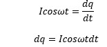
Integrating both sides, we get: 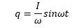
We know, Vc = q/C Putting the value of q in the above equation, we get: 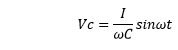
In the case of a pure capacitor, 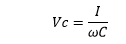
Applications of ACLet's discuss the applications of Alternating current or AC. It ranges from home to industries.
Advantages of AC over DCLet's discuss the advantages of Alternating current over direct current.
Disadvantages of AC over DCLet's discuss the disadvantages of Alternating current over direct current.
AC vs. DC
AC and DC determine the flow of current in a circuit. Let's discuss the differences between AC and DC.
Relation of AC with Pulsed DCThe pulse of DC is linear, as shown in the below image: 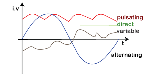
The waveform of pulsed DC has the characteristics both from the Alternating current and Direct current. Pulsed DC has varying magnitude and constant direction. A rectifier (full wave or half wave) is used to convert a pulse DC from AC. The average value of the AC is zero, while the average value of pulsed DC is constant. It is used for different purposes, such as rectification, semiconductor fabrication, etc. The primary use of the pulsating direct current is in the PWM (Pulse Width Modulation) Controllers.
Next TopicSwitch
|
 For Videos Join Our Youtube Channel: Join Now
Feedback
- Send your Feedback to [email protected]
Help Others, Please Share


