| |

AmplifierAn amplifier is a two-port electronic device used to amplify the signal or increase the power of a signal with the help of a power supply. The power is supplied through the input terminal of the amplifier. The output of the amplifier can be the increased amplitude, etc. The gain of the amplifier determines its amplification. It is the major factor that determines the output of a device. Amplifiers are used in almost every type of electronic component. The gain is calculated as the ratio of the output parameter (power, current, or voltage) to the input parameter. Amplifiers are used in various applications, such as automation, marine, sensors, etc. The power gain of an amplifier is generally greater than one. Let's understand some basic characteristics of an ideal amplifier. Here, we will discuss an ideal amplifier, types of amplifiers, properties, functions, and applications of amplifiers. Let's start. Ideal AmplifierLet's consider the characteristics of an ideal amplifier, which are listed below:
The input port of an amplifier can be the voltage source or the current source. The voltage source only depends on the input voltage and accepts no current. Similarly, the current source accepts the current and no voltage. The output will be proportional to the voltage or current throughout the port. The output of an ideal amplifier can either be a dependent current source or a dependent voltage source. The source resistance of the dependent voltage source is zero, while that of the dependent current source is infinite. The voltage or current of the dependent source only depends on the input voltage or current. It means that output voltage will depend on the input voltage, and output current will depends on the input current independent voltage source and current source, respectively. The ideal amplifiers are further categorized as CCCS (Current Control Current Source), CCVS (Current Control Voltage Source), VCVS (Voltage Control Voltage Source), and VCCS (Voltage Control Current Source). The input impedance of the CCVS and CCCS is zero, while VCCS and VCVS are infinite. Similarly, the output impedance of the CCCS and VCCS is infinite, while that of CCVS and VCVS is zero. Types of AmplifierLet's discuss the different types of amplifiers. Operational AmplifiersOperational Amplifiers or Op-amps are high-gain direct coupled (DC) amplifiers that perform various mathematical operations, such as addition, differentiation, subtraction, integration, etc. It has two input terminals and one output terminal. The input terminals are called inverting and non-inverting terminals. The signal applied to the inverting terminal will appear as phase-inverted, and the signal applied to the non-inverting terminal appears without any phase inversion at the output terminal. The voltage applied at the inverting input is represented as V- and voltage at the non-inverting input is represented as V+. Note: The output Impedance and drift of an ideal op-amp are 0. The voltage gain, input impedance, and bandwidth of an ideal op-amp are infinity.The operational amplifiers are further categorized as Inverting and Non-Inverting Amplifiers. Let's discuss the above two types of operational amplifiers in detail. ApplicationsOp-amps are used in various applications in electronics. For example,
The inverting and non-inverting input of an amplifier is shown below: 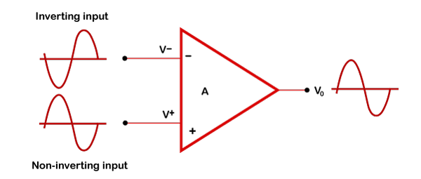
Inverting AmplifierThe inverting amplifier is shown below: 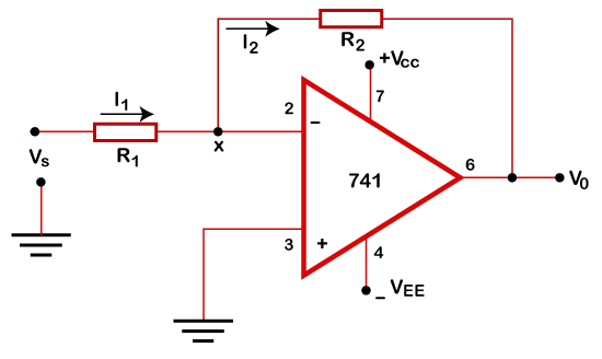
It is the voltage shunt feedback configuration of the op-amp. A signal voltage applied to the inverting input of the op-amp results in the flow of current I1 into the op-amp. We know that the input impedance of the op-amp is infinity. It will not allow the current to flow into the amplifier. The current will flow through the output loop (through resistance R2) to the op-amp's output terminal. The voltage gain at the output terminal of the inverting amplifier is calculated as: A =Vo/Vs = -R2/R1 Where, Vo and Vs are the output and signal voltage. The negative sign depicts that the output of the amplifier is 180 degrees out-of-phase with the input. Inverting amplifier is one of the most used op-amps. It has very low input and output impedances. Non-Inverting AmplifierThe non-inverting amplifier is shown below: 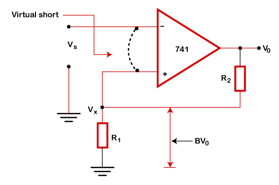
The above configuration is the voltage-series feedback connection. A signal voltage applied to the op-amp's non-inverting input results in the flow of current I1 into the op-amp and current I2 out of the op-amp. According to the concept of a virtual short circuit, I1 = I2 and Vx =Vs. The voltage gain of the non-inverting amplifier can be calculated as: A = A + (R2/R1) Non-inverting amplifiers have high input and low output impedances. It is also regarded as the voltage amplifier. DC AmplifiersDC or Direct Coupled Amplifiers are used for amplifying low-frequency and direct-coupled signals. The two stages of a DC amplifier can be interconnected by using a direct coupling between these stages. Direct coupling is a simple and easy type of connection. It can be calculated by directly connecting the first-stage transistor's collector to the second-stage transistor base, mentioned as T1 and T2. But, DC amplifiers causes two problems called drift shifting and level shifting. The design of the Differential Amplifier removed such problems. Let's discuss the differential amplifier. Differential AmplifiersThe structure of the differential amplifier solved the problem of drift and level shifting. The structure comprises two BJT (Bipolar Junction Transistor) amplifiers connected only through the power supply lines. It is named as a differential amplifier because the output of the amplifier is the difference between the individual inputs, as represented below: Vo = A (Vi1 - Vi2) Where, Vo is the output, and Vi1 and Vi2 are the two inputs. A is the gain of the differential amplifier. Now, if Vi1 = -Vi2 Vo = 2AVi1 = 2AVi The above operation is called a differential mode operation. Here, the input signals are out of phase with each other. Such out-of-phase signals are known as difference-mode (DM) signals. If, Vi1 = Vi2 Vo = A (Vi1 - Vi1) Vo = 0 This operation is known as common-mode (CM) because the input signals are in phase with each other. The zero output of such signals depicts that there will be no drift in the amplifier. Power AmplifiersPower amplifiers are also called current amplifiers. These amplifiers are required to raise the current level of an incoming signal to easily drive the loads. The types of power amplifiers include audio power amplifiers, radio frequency power amplifiers, etc. Power amplifiers are classified as Class A, Class AB, Class B, and Class C amplifiers. We will discuss the power amplifier classes later in this topic. Switch mode AmplifiersSwitch-mode amplifiers are a type of non-linear amplifier with high efficiency. A common example of such type of amplifiers is class D amplifiers. Instrumental AmplifierThe instrumental amplifier is used in analog sensing and measuring instruments. Let's consider an example. A voltmeter used to measure very low voltages requires an Instrumental amplifier for its proper functioning. It has various features, such as very high voltage gain, good isolation, very low noise, low power consumption, large bandwidth, etc. Negative feedbackNegative feedback is one of the essential features to control the distortion and bandwidth in amplifiers. The primary purpose of negative feedback is to reduce the gain of the system. The part of the output in the opposite phase fed back into the input. The value is further subtracted from the input. In the distorted output signal, the output with distortion is fed back in the opposite phase. It is subtracted from the input; we can say that negative feedback in amplifiers reduces the non-linearities and unwanted signals. The below image represents negative feedback: 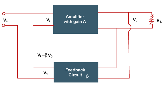
With the help of negative feedback, crossover distortion and other physical errors can also be eliminated. The other advantages of using negative feedback are bandwidth extension, rectifying temperature changes, etc. The negative feedback can be a voltage negative feedback or current negative feedback. In both cases, the voltage or current feedback is proportional to the output. We should not get confused between positive and negative feedback. Positive feedback tends to amplify the change, while negatives feedback tends to reduce the change. Another difference is that the input and output signals in positive feedback are in phase and get added. In the case of negative feedback, the input and output signals are out of phase and subtracted. Active devices in amplifierThe amplifier consists of some active devices that are responsible for the amplification process. It can be a single transistor, vacuum tube, a solid-state component, or any part of the Integrated circuits. Let's discuss the active devices and their role in the amplification process. BJTBJT is commonly known as a current-controlled device. Bipolar Junction Transistors are used as switches to amplify the current in amplifiers. MOSFETMOSFET or Metal Oxide Semiconductor Field Effect Transistors are commonly used in the amplification of electronic signals. MOSFETs can be used to change the conductivity by controlling the gate voltage. MOSFET can also enhance the strength of the weak signal. Hence, MOSFETs can be used as an amplifier. Vacuum tubes amplifiersThe vacuum tube amplifier uses vacuum tubes as the source device. It is used to increase the amplitude of the signal. Below the microwave frequencies, tube amplifiers were replaced by solid-state amplifiers around the late 19th century. Microwave amplifiersMicrowave amplifiers are commonly used in microwave systems. It is used to raise the level of the input signal with very little distortion. It can also switch or raise electric power. It provides better single device output as compared to solid-state devices at microwave frequencies. Magnetic amplifiersMagnetic amplifiers were developed in the 20th century to overcome the drawbacks (high current capacity and strength) of the vacuum tube amplifiers. Magnetic amplifiers are similar to transistors. It controls the magnetic strength of the core by energizing the control coil (another winding coil). Integrated CircuitsIntegrated circuits can hold several electronic devices, such as capacitors and transistors. The popularity of IC has also spread electronic devices all over the world. Power Amplifier ClassesPower amplifier classes are classified as class A, class B, class AB, and class C. Let's discuss a short description of the power amplifier classes. Class A power amplifiersThe input of the class A amplifier is small, due to which the output is also small. Hence, it does not produce much power amplification. With transistors, it can be used as voltage amplifiers. Class A amplifiers with vacuum pentodes can also provide a single power amplification stage to drive loads, such as loudspeakers. Class B power amplifiersBJTs generally require Class B power amplifiers to drive loads, such as loudspeakers. The input of class B amplifiers is large, due to which the output is also very large. Thus, it produces a large amplification. But, in the case of a single transistor, only half of the input signal is amplified. Class AB power amplifiersThe configuration of AB power amplifiers lies between class A and class B amplifiers. Class AB amplifiers are produced by combining the high output of class B power amplifiers with the low distortion of class A power amplifiers. In the case of small outputs, the class AB power amplifier can behave as class A. It can behave as a class B power amplifier in the case of very large outputs. Class C power amplifiersThe conduction element of class C type power amplifiers is transistors. It has better efficiency, but due to the conduction of less than the half cycle, it causes large distortion. Hence, class C power amplifiers are not preferred in audio applications. The common applications of such amplifiers include radio frequency circuits. Properties of AmplifierAmplifiers are defined as per their input and output properties. The gain of the amplifier determines its amplification. Hence, gain and multiplication factors are the two essential properties of the amplifiers. Let's discuss the properties that are defined by different parameters, which are listed below:
Functions of different amplifiersOther types of amplifiers have different characteristics. Let' discuss the function of various types of amplifiers in use today.
Applications of Amplifier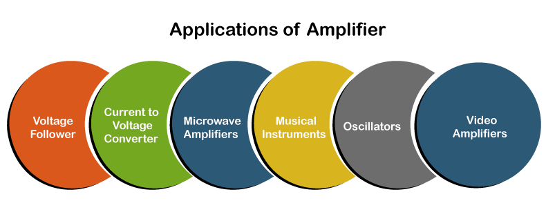
The amplifiers are used in different applications. Let's discuss it in detail.
Next TopicSphere Magnets
|
 For Videos Join Our Youtube Channel: Join Now
Feedback
- Send your Feedback to [email protected]
Help Others, Please Share


