| |

Block Diagram of Radar SystemWhat are Radar Systems?Radiating electromagnetic waves and then seeing the echo or reflected waves is how the electromagnetic-based detection technology known as RADAR operates. RADAR is referred as Radio Detection and Ranging. In the radar system, the process of finding that whether the target is present or not is referred to as detection. The target might be moving or it could be stationary. The term "ranging" describes the distance between the target and the radar. Radars have a variety of applications on land, at sea, and in space. A list of radar applications is provided below:
The fundamental idea behind radar is the same, regardless of the application. Now let us talk about the fundamentals of radar. Basic Principle of RadarThe objects are identified and their locations are determined using radar. The following illustration demonstrates how radar works in its most basic form. 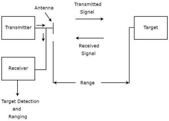
Radar primarily consists of a transmitter and a receiver, as seen in the image. The same antenna is used for both receiving and sending signals. The transmitter's job is to send the radar signal in the direction of the nearby target. This signal is reflected in different directions by the target. The receiver picks up the signal that is reflected towards the antenna. Terminology of Radar SystemsThe foundational terms that are relevant to this session are listed below.
Let's now discuss each of these fundamental terms individually. RangeThe range of the target, or simply range, denotes the distance between the radar and the target. We are aware that the target receives a signal from the radar, and in response, the target responds by sending the radar an echo signal at the speed of light, c. Let say "T" represent the amount of time needed for the signal to travel from the radar to the target and back. Because the distance between both of the radar and the target is R, the two-way distance between them will be 2R. The Speed formula is now as follows. Pulse Repetition FrequencyEvery clock pulse should be used to broadcast a radar signal. In order for the echo signal associated with the current clock pulse to be received before the next clock pulse, it is crucial to properly select the time gap between the two clock pulses. The typical form of a radar wave is shown in the accompanying figure. 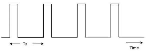
The radar transmits a periodic signal, as seen in the figure. It has several short, rectangular-shaped pulses. Pulse repetition time, abbreviated TP, is the amount of time that passes between successive clock pulses. The reciprocal of pulse repetition time is pulse repetition frequency, or fP. In Mathematics, it has the following representation: Therefore, the pulse repetition frequency is just the frequency at which the signal from a radar is sent. Maximum Unambiguous RangeWe are aware that each clock pulse should result in the transmission of a radar signal. If we select a shorter time gap between the two clock pulses, the echo signal corresponding to the present clock pulse will be received after the subsequent clock pulse. The target's range appears to be shorter than it actually is as a result. In order to ensure that the echo signal corresponding to the current clock pulse is received before the start of the next clock pulse, we must choose the time gap between the two clock pulses. This is followed by a display of the target's actual range, commonly known as the target's maximum unambiguous range or simply maximum unambiguous range. Replace R = R un and T = TP in equation 1 Run = CTP / 2 ........ (3) The pulse repetition time, TP, is obtained from Equation 2 as the reciprocal of the pulse repetition frequency, fP. In math, it has the following representation: TP = 1 / fP.........(4) Replace Equation 4 in Equation 3 Run = C(1 / fp) / 2 Run = C / 2fp ........(5) Equation 3 or Equation 5 can be used to determine the target's maximum unambiguous range. By changing the values of C and TP in Equation 3, we may obtain the value of the target's maximum unambiguous range, Run. By replacing the values of C and fP in Equation 5, we can obtain the value of the target's maximum unambiguous range, Run Minimum RangeWhen we take into account how long it takes for the echo signal to arrive to the radar after the signal is broadcast from the radar as pulse width, we will obtain the target's minimum range. It is also known as the target's shortest range. Replace R = R min and T = τ in equation 1 Rmin = Cτ / 2 ........ (6) By changing the values of C and τ in Equation 6, we can obtain the value of the target's minimum range, or Rmin. Block Diagram of Pulse RadarBasic Pulse Radar, or just Pulse Radar, is the name of the radar that uses pulse signals to identify stationary objects. During this article, let's talk about how pulse radar operates. With the use of a duplexer, pulse radar employs a single antenna to broadcast and receive signals. The block diagram for pulse radar is provided below. 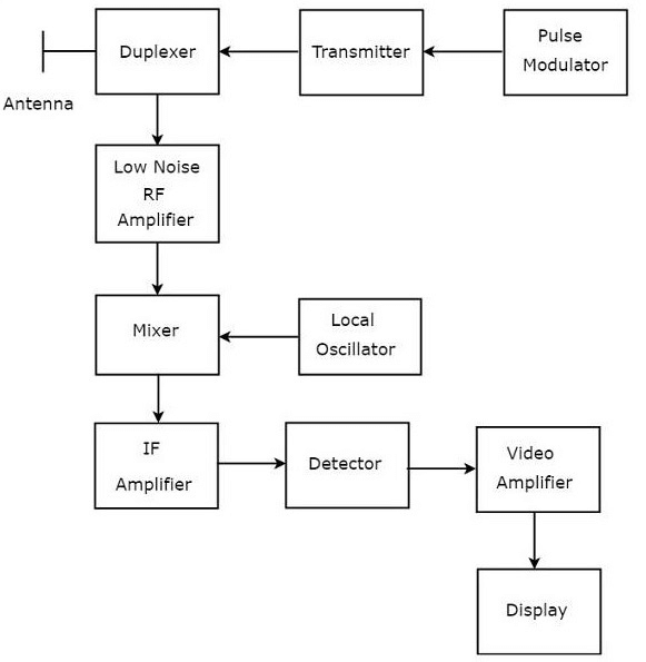
Let's examine the purpose of each Pulse Radar block now. A pulse-modulated signal is produced by the pulse modulator and applied to the transmitter. The transmitter sends out the pulse-modulated signal, which consists of a series of repeated pulses. A duplexer is a microwave switch that alternately links the antenna to the transmitter and reception sections. When the duplexer joins the antenna to a transmitter, the antenna sends the pulse-modulated signal. Similar to this, when the duplexer links the antenna and low noise RF amplifier, the signal received by the antenna will be sent to the amplifier.
We are aware that the mixer may generate both the sum and the difference of the applied frequencies. One of which will have an Intermediate Frequency (IF) type discrepancy in the frequencies. The Intermediate Frequency (IF) amplifier enhances the IF signal. Only the Intermediate Frequency, which is acquired from the Mixer and amplified, is allowed by the IF amplifier seen in the image. An improved output Signal to Noise Ratio results.
The visual signal that is acquired at the detector's output is amplified by the device known as a "video amplifier," as the name indicates. This article covered the operation of the pulse radar and how to utilize it to find stationary objects. We shall discover more about the Doppler Effect in radar systems in this article. The frequency of the signal that is emitted from the radar and is received by the radar will change if the target is not stationary. The Doppler effect is the name for this phenomenon. The Doppler effect will give us the potential outcomes of the next two cases:
Now let us calculate the Doppler frequency formula. The distance between the target and the radar is known as the range of the target, or simply range. The total distance between the radar and target on a two-way communication line will be 2R because the target transmits an echo signal to the radar and the radar reacts by sending a signal to the target. The number of wavelengths N that are present in a two-way communication line between the Radar and target will equal 2R/λ. if it is one wavelength. We are aware that one wavelength equals a two-radian angular excursion. Therefore, 4πR//λ radians will be equal to the entire angle of excursion produced by the electromagnetic wave throughout the two-way communication channel between the radar and target. The angular frequency ω mathematical formula is as follows: w= 2πf.......(1) The following equation illustrates the mathematical connection between the phase angle ϕ and angular frequency w . w= dϕ / dt......(2) Since the left-hand side terms of equations 1 and 2 are identical, compare their right-hand side terms. 2πf= dϕ / dt f= 1/2π dϕ / dt........(3) Substitute, f = fd and ϕ = 4πR/λ fd=1/2π d / dt (4πR/λ) fd=1/2π 4π/λ dR / dt fd= 2Vr / λ .......(4) Where, The Doppler frequency is fd. The relative velocity is Vr. By changing the values of Vr in Equation 4, we may get the value of Doppler frequency fd. Replace λ =C/f in Equation 4. fd = 2Vr / C/ f fd = 2Vrf / C........(5) Where, f is the signal's transmission frequency The speed of light is equal to 3* 108 m/s, or C. By changing the values of Vr, f, and C in Equation 5, we may determine the value of the Doppler frequency, fd. Note: Equations 4 and 5 shows the formula for Doppler frequency, fd, respectively. Equation 4 or Equation 5 can be used to determine the Doppler frequency, fd, depending on the provided information.
Next TopicNetwork Theory
|
 For Videos Join Our Youtube Channel: Join Now
Feedback
- Send your Feedback to [email protected]
Help Others, Please Share


