| |

BreadboardThe breadboard is a white rectangular board with small embedded holes to insert electronic components. It is commonly used in electronics projects. We can also say that breadboard is a prototype that acts as a construction base of electronics. The breadboard is shown in the below image: 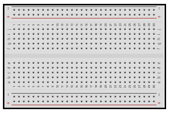
A breadboard is derived from two words bread and board. The word breadboard was initially used to slice the bread pieces. But, it was further named as a breadboard for its use in electronics around the 1970s. Hence, the term breadboard refers to these boards only and provides a quick electrical connection. A breadboard is also categorized as a Solderless board. It means that the component does not require any soldering to fit into the board. Thus, we can say that breadboard can be reused. We can easily fit the components by plugging their end terminal into the board. Hence, a breadboard is often called a plugboard. Materials usedLet's discuss the materials used for creating the breadboard. White plastic is the material that is used to create breadboards. Today, most of the breadboards are Solderless breadboards. We can directly plug in the electronic components and connect it with the external power supply. The breadboards are available as per the specified point holes. For example, 400 point breadboard, 830 point breadboard, etc. How breadboard enables the connection when the leads of different components are plugged in?There are three parts in a breadboard, as shown below: 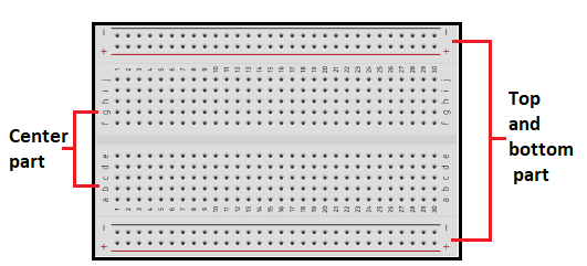
The top and bottom holes of a row in a breadboard are connected horizontally, and the center part is connected vertically, as shown below: 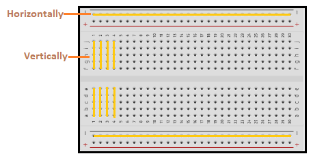
It means a single horizontal line of a breadboard has the same connection. It is because the metal strip underneath the breadboard at the top and bottom are connected horizontally. Hence, it provides the same connection in a row. The two top and bottom parts of a breadboard are generally used for power connections. The vertical connection of the center part means a single vertical line in a breadboard provides the same connection. It is useful when we need to connect the different components in series. For example, let's connect two resistors in series. These two resistors can be connected in series in different ways, as shown below: 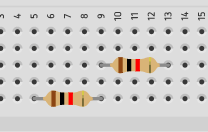
It is because the metal strips underneath the breadboard at the center are connected vertically. Hence, it provides similar connectivity through a particular column, as shown below: 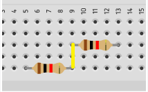
The connection between two different components can be created by inserting a lead in common. For example, a jump wire that acts as a connection between the LED and battery terminal can be connected in any hole in the same vertical line. Types of BreadboardThere are two types of the breadboard, namely Solderless and solder breadboard. Let's discuss the above two types of the breadboard in detail. Solderless breadboards As the name implies, Solderless boards do not require any soldering after the electronic components are plugged in. The leads or ends of the components are inserted into the holes of a breadboard for its functioning. Solder breadboard The solder breadboard is also a board that has a tiny hole embedded into it. We can insert the terminal of the electronic components into the board. After the connection is rechecked, we can solder these components. The common difference between solder and Solderless breadboards is the reusability. Connection setup through a breadboardHere, we will discuss the connection setup through the breadboard with the help of few examples. It will help us to understand different connections in it. Example 1: Blinking an LED The components required for the above example are an LED (any color), a breadboard, two jump wires, a resistor, and a battery. Here, we have chosen an LED of red color. The resistor is connected in series with the LED to limit the current across the LED. LED has two terminals, namely cathode (negative terminal) and anode (positive terminal). The structure of LED is shown below: 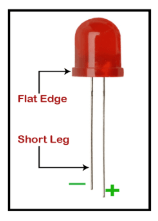
Connection Setup The connection setup is listed in the below steps:
As soon as the circuit is complete after the terminals are connected to the battery, the LED will light. The circuit so formed will appear like the image shown below: 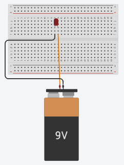
The above circuit connection depicts that the LED and resistor are connected in series. Similarly, we can easily create various projects and circuits with the help of the breadboard. Advantages of BreadboardThe advantages of using breadboard are listed below:
Disadvantages of BreadboardThe disadvantages or limitations of the breadboard are listed below:
AlternativesThere are other alternatives to create a prototype for the projects and circuit design. Modern computer systems contain various transistors, resistors, and other electronic components to create a prototype. It does not require any breadboard to build a prototype.
Next TopicPNP Transistors
|
 For Videos Join Our Youtube Channel: Join Now
Feedback
- Send your Feedback to [email protected]
Help Others, Please Share


