| |

Bridge RectifierThe bridge rectifier is a circuit that comprises four individual p-n junction diodes, alternating supply, and the load resistor. The four diodes in bridge rectifiers form a closed-loop, which is called a bridge. The bridge rectifier circuit's primary advantage is that it does not require any center tape transformer that reduces its size. The single winding is connected to the input of one side of the bridge. The load resistor to another side of the bridge, as shown below: 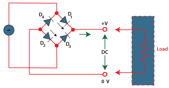
Its output waveform is similar to the full-wave rectifier. The four diodes' working depends on the positive half and the negative half of the applied input cycle. Let's discuss the construction and working of the bridge rectifier in detail. ConstructionThe diagram of the bridge rectifier includes four diodes. Let name these four diodes as D1, D2, D3, and D4. These four diodes are arranged in the series pairs. Only the two diodes among the four diodes with conduct is every half cycle. The diode D1 and D2 of a bridge rectifier during the positive half cycle are connected in forward bias. Similarly, the diodes D3 and D4 during the negative half cycle are connected in forward biased. Let's first discuss the condition of the p-n junction diode in forward biased and reverse biased. Forward BiasThe forward bias state of a diode easily permits the current flow across its terminals. It is due to the presence of the narrow depletion region. The narrow the region, the more easily it will allow the movement of charge carriers from p-region to the n-region. The polarity of a diode with its connection to the alternating input is shown below: 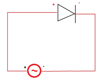
It shows that the alternating source's positive end is connected to the positive terminal of the diode. Similarly, the negative end is connected to the negative terminal of the diode. It is defined as the forward bias state of a diode. The current increases with the rise in voltage level when the diode operates in forward bias. The current flow depends on the majority carriers. Reverse biasThe reverse bias state of a diode causes the current flow in the reverse direction. It has wide depletion region. The polarity of a diode with its connection to the alternating source is shown below: 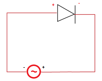
It shows that the positive end of the alternating source is connected to the diode's negative side. Similarly, the negative end of the alternating source is connected to the positive side of the diode. It is defined as the reverse bias state of a diode. The current flow depends on the minority carriers. The diode in the case of reverse bias generally behaves like an open switch. WorkingHere, we will discuss the working of the bridge rectifier separately during the positive and negative half cycle. The positive half cycleThe diode D1 and D2 become forward biased during the positive half and conducts in series. But, the diodes D3 and D4 become reverse biased. It is due to the polarity of the diode-connected with the alternating supply. The positive voltage is applied to both diodes' positive end and the negative end to the negative terminal of the diode that makes them forward biased. These two diodes conduct and correspond to the resultant output waveform, as shown below: 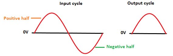
The negative half cycleThe diode D3 and D4 become forward biased during the negative half of the input cycle and conducts in series. But, the diodes D1 and D2 become reverse biased and do not conducts. The conduction of the diode D3 and D4 produces the resultant output waveform, as shown below: 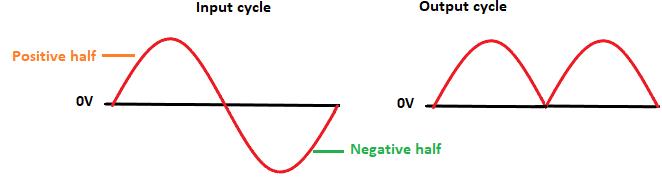
Similarly, after every positive half and negative half input cycle, the resultant output is produced, as shown below: 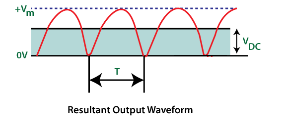
Bride rectifier AnalysisLet's discuss the parameters of the bridge rectifier. 1. Peak Inverse Voltage The PIV (Peak Inverse Voltage) of the bridge rectifier is: Vm. 2. Average and Peak Currents in the diode The forward resistance across the resistor and diode is assumed as RF and RL. The current flowing through the two diodes is: 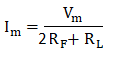
Since two diodes conduct in series, the forward resistance is 2RF. 3. Ideal Peak load current The forward resistance of the ideal diode is considered as zero. Hence, the ideal peak load current is given as: 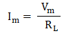
The ideal peak load current is the same of the half wave rectifier, and full wave rectifier. 4. DC Output current It can be calculated as: 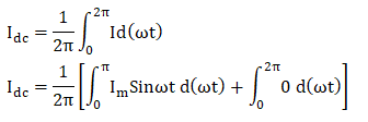
Substituting the value of Im in the above equation, we get: 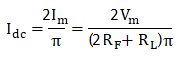
5. RMS value of the current The RMS value can be represented as: 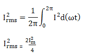
Substituting the value of Im in the above equation, we get: 
6. DC Output voltage The DC output voltage can be represented as: 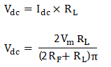
7. Rectification Efficiency Efficiency = DC power delivered to the load / AC input power from the transformer. 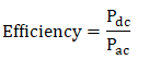
The maximum efficiency of a bridge rectifier is twice that of half wave rectifier. It is equal to 81.2%. 8. Ripple Factor The ripple factor of the bridge rectifier can be represented as: 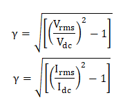
It can be expressed in the form of voltage or current. 9. Regulation The percentage regulation can be represented as: 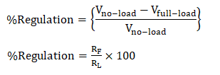
Types of Bridge RectifierThere are four types of the bridge rectifier, which are as follows: 1. Single phase Bridge RectifiersA single phase bridge rectifier comprises of four diodes, as shown below: 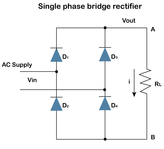
Single phase rectifiers are used to deliver small power levels. It requires a single phase alternating power supply as the input. 2. Three-phase Bridge RectifiersThree phase bridge rectifier comprises of six diodes, as shown below: 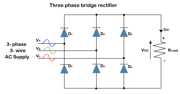
Three phase rectifiers are used to deliver large power levels. It requires three phase alternating power supply as the input. 3. Uncontrolled Bridge RectifierWe know that the diodes are unidirectional. It means that the p-n junction diode can conduct current in a single direction. The configuration of the four diodes of an uncontrolled bridge rectifier is fixed. It does not allow the variation of power. Hence, the common application of such rectifier is to provide a fixed or constant power supply. 4. Controlled Bridge RectifierThe configuration of the controlled bridge rectifier uses solid-state devices instead of diodes. The solid-state devices include MOSFET, SCR, etc., which provide varying power at the output at the load. The output power can be varied by triggering these solid-state devices at various stages. Applications of the Bridge RectifierThe applications of bridge rectifier are as follows:
Advantages of the Bridge rectifierThe advantages of bridge rectifier are as follows:
Disadvantages of the Bridge rectifierThe bridge rectifier has only one major disadvantage. It requires four diodes for its construction. It makes the rectifier circuit more complex. It also increases the voltage drop due of the rectifier circuit. The other disadvantages that can arise due to the presence of four diodes are increased loss and lower efficiency. Center tape rectifier vs. Bridge rectifierCenter tape rectifier is a type of full wave rectifier. Its function and working are similar to the full wave rectifier. Let's discuss the common differences between the center tape rectifier and the bridge rectifier.
Next TopicHalf wave rectifier
|
 For Videos Join Our Youtube Channel: Join Now
Feedback
- Send your Feedback to [email protected]
Help Others, Please Share


