| |

Half wave rectifierA half-wave rectifier is just a simple p-n junction diode connected in series with the load resistor. The circuit of the half-wave rectifier comprises of the primary and secondary windings forming the transformer, p-n junction diode, and the load resistance RL, as shown below: 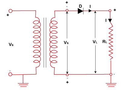
The input given to the half-wave rectifier is AC (Alternating Current). The output voltage is measured through the load resistor RL. As the name implies, the half-wave rectifier produces the half cycle of the input wave. It is due to the presence of a p-n junction diode that conducts current in only one direction. It means that the output pulse produces the output only for the positive input cycle, as shown below: 
The applications of half-wave rectifiers include pulse generator circuits, Amplitude modulation circuits, etc. Here we will discuss the detailed working of the half-wave rectifier, applications, advantages, and disadvantages. Half-wave rectifier OperationThe transformer used in the half-wave rectifier is the step-down transformer. It is used to convert AC (Alternating current) to DC (Direct Current). It has two windings, namely primary winding and secondary winding. The primary is connected to the input supply, while the secondary winding is connected to the p-n junction diode and the load resistor. The input voltage is first stepped down by the transformer and is further applied to the diode. The diode is the p-n junction diode that conducts current only when forward biased. Consider the below image that depicts the polarity of the diode when forward biased. 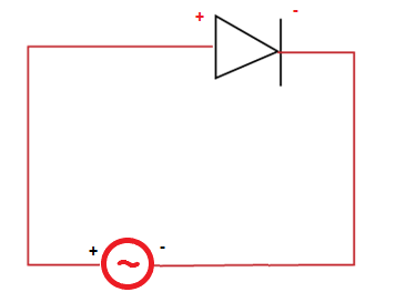
The forward bias easily allows the current to flow through the terminals of the diode. During the positive half cycle, the positive voltage is fed to the positive end of the diode. The diode becomes forward biased and produces the output. Similarly, during the negative half cycle, the negative voltage is applied to the p-n junction diode's positive end. The diode becomes reverse biased and does not conduct. Hence, we can say that the p-n junction diode produces the output only in the positive half of the input cycle. Such a process is called half-wave rectification. Working of the half-wave rectifierThe Alternating voltage across the secondary winding of the circuit changes polarity after every half cycle. During the first half cycle, the upper end of the input is positive with respect to the lower end. The diode in such case is forward biased and therefore conducts the current. If the diode's forward resistance is zero, the input voltage will be directly applied to the load resistor. In practically, the diode resistance can be minimal but not zero. The output current and voltage waveform are similar to the input AC waveform. Similarly, during the negative half, the lower end is negative for the upper end. The diode in such case becomes reverse biased and therefore does not conducts. Hence, the voltage across the load resistor remains zero. The reverse current is very small that is considered equal to zero. Thus, for every negative half cycle, no output is delivered to the load resistor. The input and output waveform for the positive half input cycle appears as: 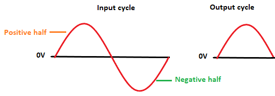
The input and output waveform for the next half (negative) input cycle appears as: 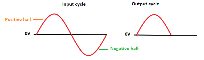
The input and output waveform for the further input cycles appears as: 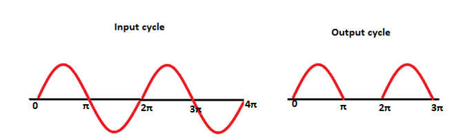
The half-wave rectifier is named because it delivers half-cycles at the output. We can also use the filter across the load to make the output wave smooth. Analysis of half wave rectifiersHere, we will discuss various parameters of the half wave rectifier. 1. Peak Inverse VoltageIt is an essential parameter in the designing of the rectifier. In reverse bias state, no current flows across the load resistor. Hence, the entire output voltage appears across the p-n junction diode. Thus, PIV (Peak Inverse Voltage) of the half wave rectifier is: Vm. 2. Average and Peak Currents in the diodeLet's consider the voltage across the transformer as secondary voltage Vs. The value given to the rectifier can be represented as: 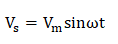
The instantaneous value of the voltage is applied to the Half Wave Rectifier. Assume to forward resistance across the resistor and diode is RF and RL. The current flowing through the load resistor is: 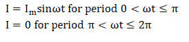
The current flowing through the diode can be represented as: 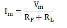
3. DC Output currentThe DC output current is given as: 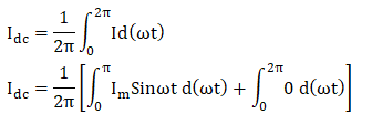
Substituting the value of Im in the above equation, we get: 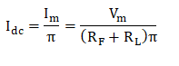
4. RMS value of the currentThe RMS value of the current flowing through the diode can be represented as: 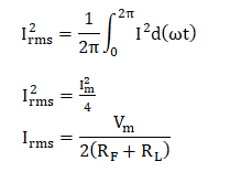
Substituting the value of Im in the above equation, we get: 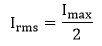
5. DC Output voltageThe DC output voltage can be represented as: 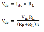
6. RMS Value of the Output voltageThe RMS value across the load is given as: 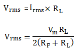
7. Rectification EfficiencyEfficiency = DC (Direct Current) power delivered to the load / AC (Alternating Current) input power from the transformer. 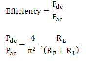
The maximum efficiency of a half-wave rectifier is 40.6%. 8. Ripple FactorIt is the ratio of the effective value of the ac components and dc components (voltage or current). It is given as: 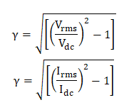
9. RegulationIt can be represented as: 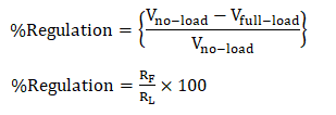
ApplicationsThe rectifiers are generally used to construct DC power supplies. The rectifier can be a half-wave or full-wave rectifier, depending on the requirements. Both the rectifiers are used as a component in building DC power supplies. The full-wave rectifiers are proffered for smooth DC power supply applications. In applications where there is no requirement for a smooth or constant DC power supply, we can use the half-wave rectifier. The Half Wave Rectifier's other applications include soldering iron circuits, small battery cells, AM (Amplitude Modulation) radio circuits, firing circuits, etc. Advantages of Half wave rectifierThe circuit of the half-wave rectifier is simple and cheap. It is easy to construct. Let's discuss the advantages of the half wave rectifiers. 
DisadvantagesThe disadvantages of a half-wave rectifier are as follows:
Hence, a half-wave rectifier is not recommended for the general power supply due to all the above disadvantages. It is used for some applications, such as soldering iron circuits, low power batteries, pulse generator circuits, etc.
Next TopicWhat is Format Factory
|
 For Videos Join Our Youtube Channel: Join Now
Feedback
- Send your Feedback to [email protected]
Help Others, Please Share


