| |

Clampers (electronics)The clampers are used to add the dc level to the ac input signal. The input swing of a waveform is equal to the output swing. But, sometimes, it becomes necessary to add a certain dc level to an ac signal. The circuits possessing such capability to increase the signal level are known as clamper circuits. The clamper circuits are also known as dc restorer circuits or dc inserter circuits. The basic elements of a clamper circuit are diodes, resistors, and capacitors. The diode conducts the current in a particular direction and prevents the circuit from high voltages. The resistor limits the current for the diode, and the capacitors are the charge storage elements. The input waveform of most circuits is AC sinusoidal waveform. The ac level is the level of the sinusoidal AC waveform. Thus, it is termed as the ac level. The DC level is added in the input signal that shifts the waveform to the desired level (upward or downward) without changing the width of the signal. It is called as DC inserter because it adds a DC voltage level to the output waveform. We can also say that clamper adds value to the Y-axis of the signal waveform. The steps to analyze the clamper circuits are as follows:
Types of ClampersThe clampers are classified as positive clampers and negative clampers. It is based on the positive dc shift or negative dc shift. Positive ClampersThe circuit of the positive clamper is shown below: Where, RL is the load resistance Vin is the input voltage Vout is the output voltage Vm is the maximum voltage of the capacitor D is the diode The positive and negative terminals of the diode are shown below: 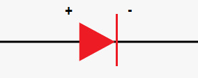
Input waveform The input waveform consists of the positive half and the negative half. The positive half lies above the positive x-axis and the negative half lies below the x-axis, as shown below: 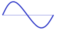
It is the sinusoidal waveform. The waveform with respect to the axis is shown below: 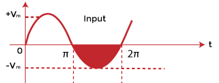
The colored part represents the negative half and the upper part represents the positive half. Working When the negative half of the input voltage is applied to the clamper circuit, the diode D conducts and becomes forward biased. It is the state where the positive connection of the voltage comes in contact with the positive terminal of the diode. The capacitor gets charged to the maximum voltage Vm. The polarities of the capacitor with the negative input voltage are shown below: 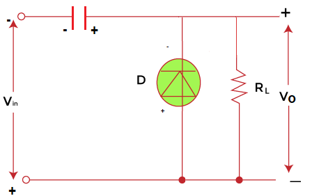
The diode at the conducting stage becomes q short circuit, as shown below: 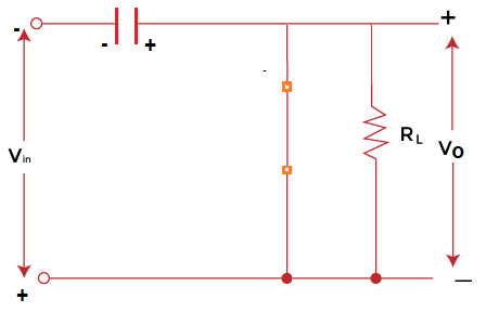
The capacitor stores the energy to the maximum value when fully charged. The large RC constant value helps the capacitor store the charge for a long duration. The stored energy is utilized when the diode is in an OFF state. During the positive half of the input voltage, the diode becomes reverse biased and does not conduct. It is the state when the positive input voltage is connected to the negative terminal of the diode. The input voltage at this stage is equal to the capacitor voltage. Vin = Vm The output voltage can be represented as: Vo = Vin + Vm Vo = Vm + Vm Vo = 2Vm If the input voltage during the positive half of the input cycle is -Vm, the output voltage will be 0. Vo = Vin + Vm Vo = -Vm + Vm Vo = 0 Output waveform The input and output waveforms are as follows: 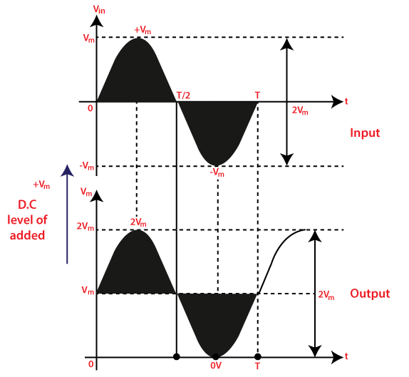
Negative ClampersThe circuit of the negative clamper is shown below: 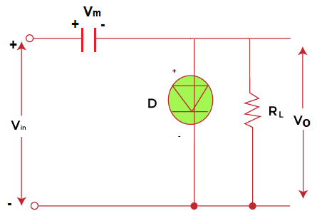
Where, RL is the load resistance Vin is the input voltage Vout is the output voltage Vm is the maximum voltage of the capacitor D is the diode The negative clamper can be achieved by reversing the orientation of the diode in the positive clamper circuit. The behavior of the diode is considered as ideal. Working When the positive half of the input voltage is applied to the clamper circuit, the diode D conducts and becomes forward biased. The capacitor gets charged to the maximum voltage Vm. The voltage applied to the capacitor is continuous due to the large value of the RC constant. The polarities of the capacitor with the positive input voltage are shown below:
The output voltage is zero during the first positive half. The input voltage starts decreasing after attaining its maximum value Vm. The capacitor charges to the maximum value and remains constant. Thus, the capacitor voltage is given by: Vc = Vm When the input voltage decreases to a level below the maximum value, the capacitor starts providing the stored charge to the diode. The opposite polarity of the capacitor and the diode makes a reverse biased connection. It turns OFF the diode. The clamper circuit when the diode is in non-conducting state is shown below: 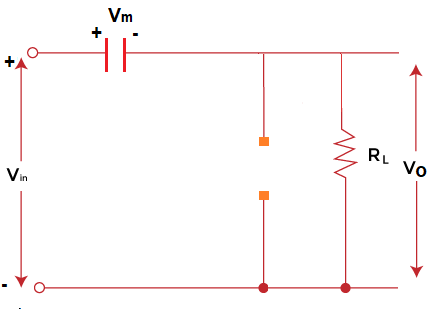
The diode becomes a short circuit during conducting state and an open circuit during the non-conducting state. During the negative half of the input voltage, the diode will remain reverse biased and do not conduct. The capacitor starts losing its charge through the load resistance RL. Thus, for the negative half cycle, the input voltage is zero. The output voltage is given by: Vo = Vin - Vc Vo = Vin - Vm Vo = - Vm If, Vo = Vin - Vm = 0 Vin = Vm During the positive half cycle, The output voltage can be represented as: Vo = Vin - Vc Vo = Vin - Vm Vin is equal to -Vm for the positive half cycle and adds a negative dc level. Vo = -Vm - Vm Vo = -2Vm Output waveform The input and output waveforms are as follows: 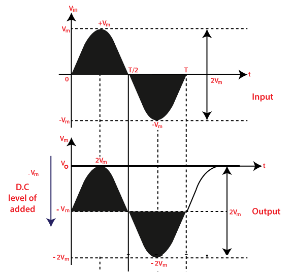
The working of clamper circuits can vary when a battery is added. Let's discuss the function of battery in detail. Addition of battery in the clamperThe dc value can be added to a fixed value Vm in the positive and negative clippers. But, the addition of battery in the clamper circuits can help it to control the shape and dc level of the output waveform. The circuit is the same as the above clampers circuits, except for the additional battery. The positive clamper circuit with the battery is shown below: 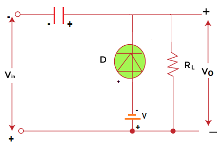
The battery is connected in series with the diode. Here, RL is the load resistance Vin is the input voltage Vout is the output voltage Vm is the maximum voltage of the capacitor V is the voltage of the battery Working When the negative half of the input voltage is applied to the clamper circuit, the diode D conducts and becomes forward biased. The conducting state of the diode occurs when the input voltage is less than the battery's voltage. The capacitor gets charged when it receives the voltage, which is given by: Vc = Vin - V Vc = Vm - V During the positive half of the input voltage, the diode becomes reverse biased and do not conducts. The node of the diode becomes open circuit during the non-conducting state, as shown below: 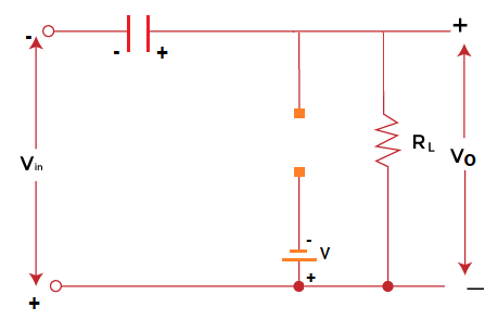
Applying KCL to the above circuit, we get: Vc - Vo + Vin = 0 Vo = Vc + Vin Putting the value of Vc in the above equation, Vo = Vm - V + Vin We can also say that Vm - V is added to the input of the clamper circuit to produce the output. We know, Vin = Vm So, Vo = 2Vm - V If Vin = 0 Vo = Vm - V If Vin = -Vm Vo = -V Output waveform The input and output waveforms are as follows: 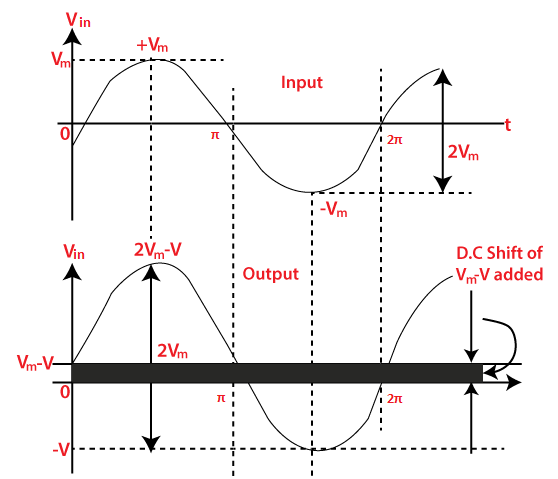
Advantages of ClampersThe advantages of clampers are as follows:
Clampers vs. ClippersLet's discuss the differences between the clampers and the clippers circuit.
Next TopicJava Rain Resorts
|
 For Videos Join Our Youtube Channel: Join Now
Feedback
- Send your Feedback to [email protected]
Help Others, Please Share


