| |

Common baseCommon base BJT (Bipolar Junction Transistor) amplifiers are BJT with the common or grounded region as the base. Based on this, BJT is also classified as a common emitter and common collector amplifier. The emitter region is the input in the common base amplifier, and the collector region is the output. The base is connected to the ground as the common terminal to both the input and the output and thus named common base amplifier. BJT amplifier as the common base has low input impedance but produces high output impedance. It has various applications, such as a current buffer and microphones. First, let's discuss the amplifiers and the requirement of using the base region as the common base. AmplifiersThe amplifier is an electronic device that amplifies the input signal and produces the desired output. Amplifying refers to the increase in the power or the voltage of the input signal. Amplifiers take energy from the external connected power supply, control the output, and produce the output waveform with large amplitude. There are various types of amplifiers such as current amplifier (amplifies the input current), voltage amplifiers (amplifies the input voltage), transresistance amplifier (amplifies the input current to the output voltage), and the transconductance amplifier (amplifies the input voltage to the output current). BJT AmplifiersBJT works as an excellent amplifier generally in the active forward mode. It provides the high output voltage, power gains, and current. A small input voltage to the emitter region of the BJT provides a large output voltage. Thus, Bipolar Junction Transistors provide good amplification. Common Base TransistorHere, we will consider a common base amplifier of an NPN transistor. It consists of a P layer (doped with trivalent impurity) sandwiched between two N layers (doped with Pentavalent impurities). Circuit connectionThe circuit of the common base BJT is shown below: 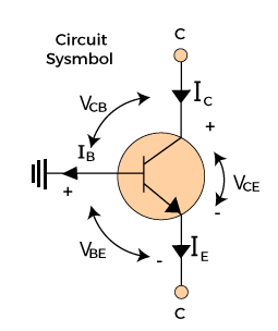
The three regions of the BJT are emitter (E), base (B), and collector (C). The two voltage sources are connected between the three regions. The voltage source connected between B and C is VCB and the voltage source connected between B and E is VBE. The current from the E and C regions are represented by IE and IC. Since, the base region is grounded (0 Volts), it has no current. 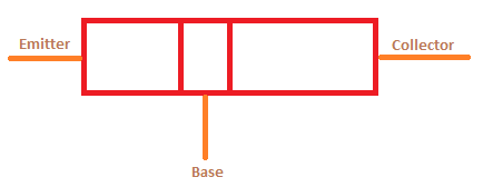
Note: Common base amplifier is a type of BJT only with the common base between the input and the output.The doping concentrations of these three regions are: Collector: Lightly doped, largest width Base: Medium doped, smallest width Emitter: Highly doped, medium width WorkingThe input of the common base is the E region. The electrons from the voltage source VBE flows towards the E region. It is an N-type and thus contains electrons as majority carriers. The electron from the E regions starts moving towards the B due to repulsion between the same charge carriers at the junction. The B region is small to hold such large concentration of carriers and passes it further to the collector. The collector does not have its own current due to the reverse-biased connection. EquationsThe ratio of the collector current and the emitter current is given by: IC/IE = a Where, a is the common-base current gain (a < 1). The ratio of the collector current and the base current is given by: IC/IB = B Where, B is the common-emitter current gain (B > 1). The equation of the common base transistor is given by: IE = IB + IC ParametersThe equivalent circuit of the common base amplifier is shown below: The current gain of the common base amplifier is less than 1. The AC equivalent circuit is shown below: 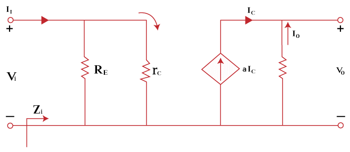
The above circuit diagram is drawn by keeping all the DC (Direct Current) sources as a short circuit. The parameters like voltage gain, current gain, input, and output impedance will be calculated based on the above circuit diagrams. Voltage GainVO = -IO VO = ICRC IC/IE = a IC = aIE Putting the value of collector current in output voltage, we get: VO = aIERC The emitter current is given by: IE = VI/re So, the output voltage is: VO = a(VI/rc)RC Gain = Output voltage/Input voltage AV = VO/VI = aRC/rC Current gainThe current gain is given by: Output current/Input current AI = IO/II The collector region is the output region. Thus, the output current depends on the collector current. IO = -IC We know, IC = aIE So, IO = - aIE The emitter region is the input region. Thus, the input current depends on the emitter current. II = IE So, gain is: AI = IO/II AI = - aIE / IE AI = - a Input ImpedanceThere are two resistance connected across the input, RE and re. The input impedance ZI is given by: ZI = RE||re It is the parallel connection of the two resistances RE and re. Output ImpedanceThe output resistance is the resistance connected across the output of the above equivalent circuit of the common emitter. There is only resistance connected across the output, i.e., RC. Thus, the output impedance is given by: ZO = RC We will also discuss examples based on the above parameters later. Low-frequency parametersThe low-frequency common base amplifier is shown below: 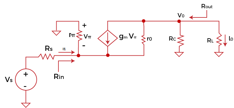
The low-frequency parameters of the common base amplifier are listed as follows: Open-circuit voltage gainThe voltage gain is a unitless quantity and is defined as the ratio of output voltage to input voltage. Voltage gain = Output voltage/Input voltage It is given by: Av = (gmro + 1)RC/ (ro + RC) If ro in greater than Rc, the voltage gain will be: Av = gmroRC/ro Av = gmRC Short-circuit current gainThe current gain is defined as the ratio of output current to input current. Voltage gain = Output current /Input current It is given by: Ai = (rπ + Bro)/ (rπ + (B + 1)ro) If B in greater than 1, the current gain will be: Ai = (rπ + Bro)/ (rπ + (B)ro) Ai = 1 Input resistanceWe know, I = V/R Or R = V/I The input resistance can be represented as: Ri = Vi/Ii Ri =((ro + RC ||RL)RE) / (ro + RE + RC ||RL/(B + 1)) Output resistanceThe output resistance can be represented as: Ro = Vo/-Io Ro = RC || ([1 + gm (rπ || RS)] ro + rπ || RS) If, ro is less than rE, the output resistance will be: Ro = RC || ro If, ro is greater than rE, the output resistance will be: Ro = RC || ([1 + gm (rπ || RS)] Common base as a current followerThe current follower is also known as the current buffer, which follows the input current. If the output current of the transistor follows the input current, it is known as a current follower. If produced by the load, it is not affected by any current or voltages. The circuit of the current follower is shown below: 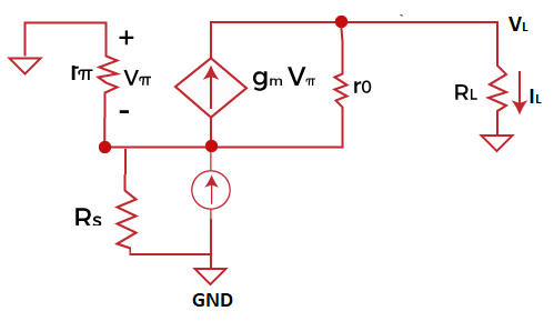
The Common base Bipolar Junction transistor is a bilateral transistor. The AC source is connected at the input, and the load resistance is connected across the output. The output resistance Ro connects the input and the output. If the collector resistance is present, the output resistance of the transistor will still be large. It follows the current division at the output and allows the majority current to pass through the load transistor. It is one of the essential conditions for the transistor to work as a current follower. The current gain may reach unity as long as AC source resistance at the output is large as compared to the emitter resistance. The current gain of the BJT current follower is unity. Common base as a voltage amplifierThe common base amplifier also works as a voltage amplifier. According to the common base as a current follower, the high output resistance allows the majority current to pass through the load transistor. It is an ideal condition for the common base to work as a current follower. But in the case of voltage, the high output resistance is not the desirable condition for the voltage division at the output. The voltage gain can be calculated for a small load and large impedance values. IN the case of large impedance, the voltage gain is determined based on the load resistance and input resistance (RL/Rs) ratio. As discussed above, if the AC source replaces the Thevenin voltage source, the common base transistor as a voltage amplifier starts behaving like the current follower. ApplicationsThe applications of the common base are as follows:
ExamplesLet's discuss an example based on the common base BJT amplifiers. Example: The configuration of the common base transistor is given below: 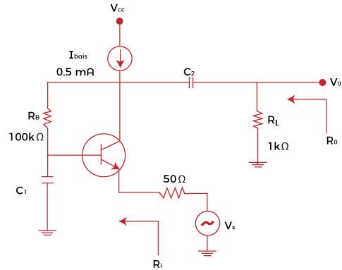
Find the voltage gain, input impedance, and output impedance of the circuit. Assume that the transistor is ideal. Solution: Voltage Gain Voltage Gain is given by: Output voltage/Input voltage Since the given transistor is ideal, we have assumed the input and output current to be equal. So, the voltage gain is: Av = (1 k Ohms) || (100 K Ohms) / Re Av = 990 Ohms/ 52 Ohms Av = 19.03 or 19 Gain is a unitless quantity and thus has no units. Input Impedance The input impedance can be calculated using the formula: IE = VI/re Ie = 0.5 mA =0.5 x 10⁻³A Vt or threshold voltage = 26Mv = 26 x 10-3V So, Re = V/Ie Re = 26 x 10-3V/0.5 x 10-3A Re = 52 Ohms It is the resistance across the input, i.e. emitter region. The input impedance of the transistor is the resistance of the emitter region = Re = 52 Ohms. Output Impedance The output impedance is the equivalent resistance value of the resistors connected across the output of the transistor. There are two resistors connected across the output. Thus, the output impedance is: Zo = (1 k Ohms) || (100 K Ohms) Zo = 1 x 100/ (1 + 100) K Ohms Zo = 100/101 k Ohms Zo = 0.990 k Ohms Zo = 0.990 x 1000 Ohms Zo = 990 Ohms
Next TopicWhat is a cell
|
 For Videos Join Our Youtube Channel: Join Now
Feedback
- Send your Feedback to [email protected]
Help Others, Please Share


