| |

DC MotorDC motor or Direct Current Motor is a device that converts the direct current energy into mechanical energy. The energy generated through the current is used to drive the motor. The DC motor is considered the simplest motor with continuous angular rotation, which has various applications ranging from households to industries. Examples include an electric window in cars, machine tools, printers, electric vehicles, elevators, etc. Here, we will discuss the working of DC motor, categories, and types of DC Motor. 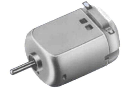
The rotation of DC Motor can be controlled, which makes it ideal for Motor use in different categories. The operation of most of the DC motors depends on the magnetic field forces. Let's discuss how the DC motor works. Working of a DC MotorThe working of DC Motor depends on the received electric current. It will continuously rotate as long as electric current flows through its circuitry. Here, we will discuss the working of a DC Motor in detail. PrincipleWhenever a conductor (allowing the flow of current) is placed in a magnetic field (that signifies the magnetic effect on current), it experiences a torque that causes the motor to rotate. The direction of rotation of the DC Motor was given by an English Electrical Engineer named John Ambrose Fleming. The rule is called Fleming's left-hand rule. According to Fleming's rule, we can easily find a parameter (force) if the directions of the other two parameters (Current and magnetic field) are known. ComponentsThe major components of a DC Motor are Armature, Stator, Brushes, and Commutator. StatorThe stator is the stationary or fixed part of a DC Motor. It provides a magnetic field to the Armature, which is concentrated on the core. The stator of a Motor can either be an electromagnet (created from the core with insulated wire windings) or a permanent magnet. The core of an electromagnet consists of the wrapped windings of copper wire. The magnetic field is generated when current passes through the windings of the core. The magnetic energy flows to the Armature that creates motion. The coil of a DC Motor is generally a metal core, which is either aluminum or iron. The metal as a core increases the magnetic flux density. The insulated wire windings material is generally copper wire. Today, we can also use a magnet wire, a copper wire but with a thin coating. We generally prefer copper wire as the winding material because it reduces loading losses. ArmatureThe Armature is a rotary part of a DC Motor. The magnetic field produced by the stator helps the Armature to rotate. The Armature of a DC motor interacts with the magnetic field produced by the stationary magnets in the air-gap. The Armature is oriented to the force, torque, field, and direction of motion. The Armature carries current; hence it is always a conductor that permits the current flow. We can either use a metal loop as an armature or any other conductor with wire windings. For example, a metal core with the windings of insulating wires. CommutatorIt is defined as a power switch in the DC Motor that applies an electric current to the windings on the Armature. A commutator is a ring with gaps on the opposite sides, as shown below: 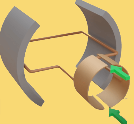
It reveres the direction of current flowing between the Armature and external circuitry. It is in the form of metal segments, which are in contact with the Armature. A DC motor with a single armature loop has two commutator segments attached with the two ends of the armature coil. The commutator picks up the current from the Armature and reverses the direction of the current after every half turn. It produces the torque. DC Motors also comes with brushes that are attached to the commutator. Let's understand the brushes. BrushesBrushes are attached at the side of the commutator. There are two brushes at both sides of a DC Motor that will slide along with the commutator rotation. The Brushes are made of precious metal, such as graphite, to improve its conductivity. The brushes are spring-loaded at the end to maintain the pressure that helps it to always maintain contact with the commutator. WorkingThe role of the magnets is to produce the magnetic field, which flows to the Armature. The electromagnet (Armature) works like a magnet flap. The commutator is attached to the Armature, which is a ring with gaps on the opposite sides. The brushes are connected to the battery with the wire that completes the circuit, as shown below: 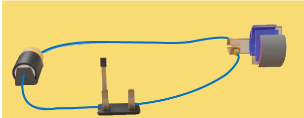
The current is generated from the battery, flows from the wire to the brush. The brushes pass the current to the commutator ring and further to the Armature. The same happens through the other side. Now, the electromagnets rotate as the armature spins. Armature receives energy from the stator and spins. It will continue to spin until opposite poles are lined up. The commutator will rotate along with the Armature. The two brushes attached at the side of the commutator will also spin. It is shown below: 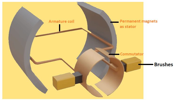
After it completes half rotation, the brushes will shift to the other side of the commutator ring. Due to the presence of two brushes, it will happen on both sides. The current reverses the direction after the brushes switch the side. It will cause the electromagnet to switch the polarity, which causes the Armature to continue spinning. The commutator, this time, will continue to spin on its own. It will continue to rotate as long as the connection is complete and connected to the battery. The spinning stops when we disconnect a battery. A single electromagnet may cause irregular speed. We can also add another conductor loop or coil in the Armature. It will result in the addition of two more commutator segments. It means for two loops; there will be four commutator segments. Some DC Motors come with many conducting loops in the Armature. It ensures continuous spinning motion in the motor. DC Motor CategoriesThere are four categories of DC Motor, which are listed below:
Let's discuss the above categories of DC motors in detail. Permanent Magnet Type DC MotorA permanent magnet type DC Motor works the same as other types of DC Motor. It uses a permanent magnet as a stator instead of an electromagnet. It means the structure of such a type of motor comprises a stator (permanent magnets), Armature, brushes, and commutator. The permanent magnets are responsible for providing a magnetic field against which Armature interacts to produce torque. The permanent Magnet type DC Motors cannot be used for speed control due to its fixed magnetic field. It is generally used to eliminate the use of power consumption required by the field winding. High energy magnets are preferred to reduce the weight and size of the motor. Brushed MotorThe structure of the Brushed Motor is similar to the brushless motor except for the addition of brushes. The Brushed DC Motor has a low initial cost and easy motor control speed. Let's discuss the working of the brushed motor in detail. It comprises of stator, Armature, brushes, and commutator. The stator is the fixed part of a motor, while Armature is the rotary part. The Armature is generally a rotating electromagnet. Brushes are attached at the side of the commutator. There are two brushes on both sides of a DC Brushed Motor. Brushless MotorBrushless Motor is the same as the brushed motor but without any brushes. It also comprises three essential parts called stator, Armature, and commutator. The design of a brushless Motor is simple as compared to a brushed motor. WorkingThe stator is the fixed part of a Motor that can either be an electromagnet or permanent magnet. An electromagnet is composed of the metal core with the windings of the copper wire. It generates a magnetic field when an electric current passes through the coil. The electromagnet's magnetic property can be controlled by adjusting the current or switching the circuit ON/OFF. The role of these two magnets is to produce the magnetic field, which flows to the Armature. The Armature can be a conducting loop or a coil with windings of wire wrapped around it. The commutator is attached with the Armature. The armature ends are connected to the wire that completes the circuitry. As soon as the current passes through the Motor, Armature starts rotating. The commutator also rotates along with the armature rotation. Without a commutator, it becomes difficult to manually rotate the Armature. Let's discuss some differences between Brushed and Brushless Motor, which are listed in the below table.
Uncommutated DC MotorUncommutated type of DC Motors does not require any computation. It is further categorized into homopolar and ball bearing motors. Homopolar terms signify the constant polarity and works without the use of a commutator. It means that the coil rotates only with a single turn. Hence, such type of motors is not in any practical use. The ball bearings motor consists of two ball bearings with inner and outer races, which are mounted to the conducting shaft and power supply. The power supply has a high current and low voltage. Such motors' inner and outer races can also be mounted to a non-conducting shaft and inner metal tube. The tube working as a flywheel is a major advantage of the ball bearing motors. Types of DC MotorThere are three types of DC Motor, which are listed below:
The types of motor determine the connection of the stator with the Armature or rotor. Let's discuss the above types of DC Motors with its characteristics in detail. Series DC MotorIn Series DC Motor, the connection of field winding and rotor are in series. The number of turns of copper wire (insulated wire) is less, which can easily carry full load current to the DC Motor. Thus, the windings of the series motor have low resistance. Due to low resistance, the current at the starting produces high torque. Hence, DC series Motors are often recommended for their high starting torque capability. For example, cranes are used to pick heavy materials. The diagram of the series DC Motor is shown below: 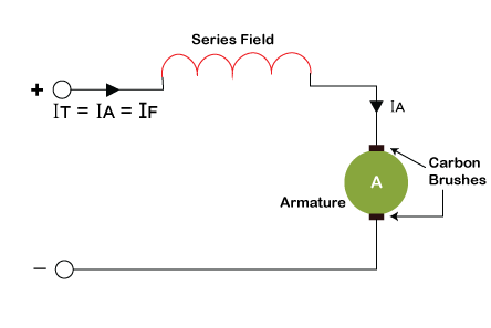
Applying KCL to the above diagram, we get: I=Ia=If Where, Ia isthearmaturecurrent If isthefieldcurrent I is the input current Applying KVL: V=E+I(Ra+Rf) Where, Ra isthearmatureresistance Rf isthefieldresistance Shunt DC MotorIn Shunt DC Motor, the connection of field winding and rotor are in parallel, as shown below: 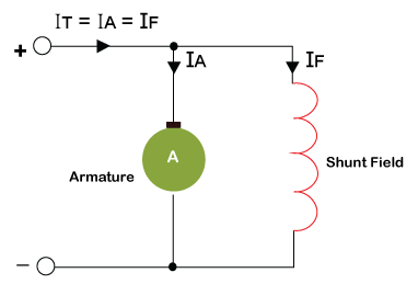
Many turns of copper wire (insulated wire) are mounted, which provides a constant current to the motor. The starting of shunt DC Motor is less as compared to series DC Motor. Hence, it is preferred for constant speed operations. Let's start with its characteristics. Applying KCL to the above diagram, we get: I=Ia+If Applying KVL to get the equation of the field winding: V=If Rf Applying KVL to get the equation of armature winding: V=E+Ia Ra Compound DC MotorIn Compound DC Motor, the motor's field winding is connected in parallel but with few turns of copper wire mounted on it. The characteristic of Compound DC Motor is obtained by combining the characteristics of both series and shunt DC Motor. The sires and shunt field winding of the compound DC Motor are connected in series and parallel with the Armature, as shown in the below diagram: 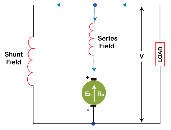
Advantages of DC motorsThe advantages of DC motors are listed below:
DC Motors vs. AC MotorsWe have discussed the advantages and disadvantages of DC Motor. But, we must be confused about its use compared with AC motors. AC Motors and DC Motor works similarly by converting electrical energy into mechanical energy. But, the construction and power source of both these motors are different. So, let's discuss some differences between DC Motors and AC Motors.
Next TopicIptables commands
|
 For Videos Join Our Youtube Channel: Join Now
Feedback
- Send your Feedback to [email protected]
Help Others, Please Share


