| |

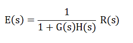
PID ControllerPID controller is a combination of the Proportional, Integral, and Derivative control modes. It is the most powerful controller action that is a combination of all three modes. PID controller is based on the control loop feedback mechanism. It is used in various applications that require modulated control in a continuous form. The feedback control system improves stability, meet performance specifications, improve disturbance rejection, etc. PID controller specifies how the performance specifications are affected by adjusting the three controllers' gain (Proportional, Integral, and Derivative). Let's first discuss what controllers are. ControllersThe controllers decide the kind of actions taken in response to an error. A controller generally uses the difference between set point (SP) and measurement signal to develop the output signal. A controller serves as the front end in the closed-loop control system operation. The block diagram representation of a closed-loop system is shown below: 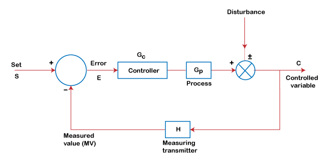
The three operations are responsible for achieving the desired control action, which is listed below:
Mathematical Expression of PID ControllerThe analytical expression of the PID Controller can be written as: 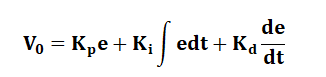
Taking the Laplace transform of the above equation, we get: 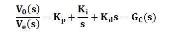
The three terms used in the expression (Kp, Ki, and Kd) are the gain of the Proportional controller, Integral controller, and the Derivative controller. We know that the PID controller is a combination of these three controllers. Hence, the equation formed is the combination of the proportional gain, integral gain, and derivative gain. Let's discuss the three controllers in detail. Proportional ControllerThe output in the proportional controller is directly proportional to the input. It is considered as the most common controller action where the output is directly proportional to the input. Here, the input is the error signal. The basic equation of the proportional controller is: Error = Set point (r) - measured value (c) m=Kpe+mo Where, m is the controller output Kp is the proportional gain constant mo is the controller output with no error percentage The transfer function can be written as: Gc(s) = Kp The controller's output depends only on the size of the error at the instant of the concerned time. The block diagram of the system is shown below: 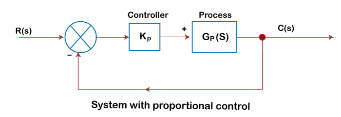
The constant gain tends to exit only over a certain range of errors. Such a range is called a proportional band. It is given by: Kp = 100/Proportional Band (PB) AdvantagesThe advantages of the proportional controller are listed below:
Characteristics of Proportional ControllerThe characteristics are listed below:
Integral Controller Integral control is used when we want the controller action to correct from any steady and continuing offset to the desired reference signal. The block diagram of the Integral Controller is shown below: 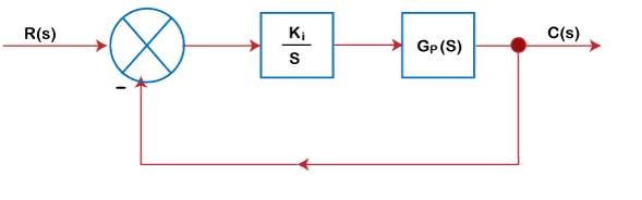
The steady state error cannot be 0 until the proportional gain is not equal to infinity. But, it is practically impossible. So, without the excessive increase of Kp, the Integral Controller can increase the controller output. The output will be: 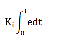
Let us assume the output of the controller as: 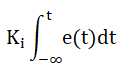
The steady state error of the Integral controller is 0 when the value of Kp approaches to infinity, as shown below: 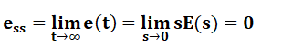
From the above statement, we can conclude the following:
Thus, we can say that: The addition of an integrator to the system or the pole at the origin reduces the steady-state error to zero. But, it may not work for higher-order systems. The Integral controller's main advantage is the increase in the system type by one, as discussed above. Derivative ControllerIt is used when the controller needs to have the rate of change of the error (e) signal in control action. It has the derivative form, where the controller output is proportional to the error (e) with time. It is expressed as: Output = Kd de/dt Where, Kd is the derivative gain. The output of the derivative controller does not depend on the past or present error. Instead, it depends on the rate of the changing error. A derivative controller can provide a large corrective action before a large error occurs. If the error is constant, corrective action cannot take place. The derivative controller needs care for its operation. It works with a small gain. A rapid change of error in the derivative controller can cause large or sudden changes in the controller output. Characteristics of the Derivative Controller
Let's consider an example. Example: Consider the system with G(s) = 1/Js^2 as a rotational element with J as the moment of Inertia. It depicts that the poles lies on the imaginary axis if we increase the gain from zero to infinity. The response of the system in this case is purely oscillatory. Proportional-Derivative ControllerThe analytical expression formed contains the gain of the two controllers, Proportional and Derivative. It comprises of gain constant, as shown below: 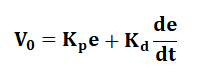
The Proportional-Derivative controller is used to remove the oscillations that occurred in the Derivative controller. It is also allowing a higher proportional gain setting. Let's consider the block diagram of PD controller. 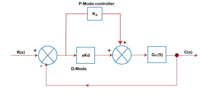
CharacteristicsThe characteristics of the Proportional Derivative controller are as follows:
Proportional Integral ControllerThe proportional Integral controller is generally used in slow-to-moderate speed processes. We know that an Integral controller tends to reduce the relative stability of the system. It can be overcome by adding a proportional controller to it. The block diagram of the Integral controller is shown below: 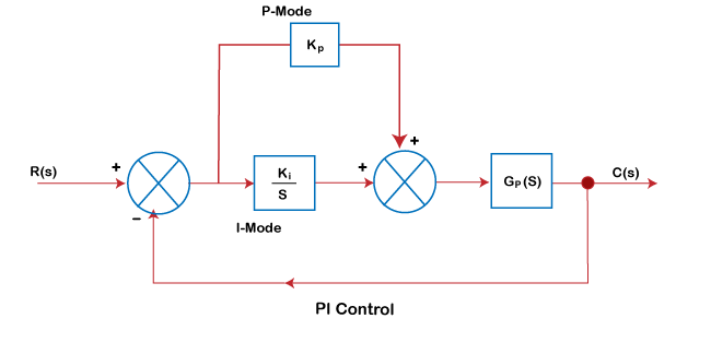
Thus, the Integral controller is frequently combined with the proportional mode to provide the automatic next action that eliminates the proportional offset. The output of the PI controller is the combination of their respective gain constants, as shown below: 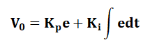
The PI controller is also used on processes with a large load change when the proportional mode cannot reduce the offset to the desired level. The proportional offset is eliminated by the reset action provided by the Integral controller. Applications of PID ControllersPID controllers are used in various applications to regulate different process variables, such as temperature, pressure, and speed. Let's discuss some common applications of the PID controllers.
Advantages of PID ControllersThe combination of the three controllers gives the perfect tracking of the system. Let's consider some advantages of the PID controllers.
Next TopicSolder
|
 For Videos Join Our Youtube Channel: Join Now
Feedback
- Send your Feedback to [email protected]
Help Others, Please Share


