| |

What is Pen Table?The pen table is ASCII text files that contain instructions for resymbolize the printed output of design files. The instructions are contained in sections within the pen table. Pen tables are created or modified automatically by using the Pen Table dialogs. Resymbolization is the process of changing the characteristics of elements within a design file. When these changes are applied to printed output, the process is referred to as print resymbolization. Pen tables control print resymbolization. Pen tables are used to change the characteristics of elements for printed output. For each pen table section, there are element selection criteria and a set of element output actions. During the creation of printed output, the pen table tests for specific types of elements and characteristics. If such elements are found, the pen table will modify, enhance, or eliminate these elements and their characteristics. The testing criteria include:
Evaluation of elements is based on the specified criteria. Many elements, such as level, can have multiple values and ranges of values. How to Create a Pen Table?Below are the following steps to create a pen table: Step 1: Open the Print dialog's Resymbolization menu. Step 2: And choose New Pen Table. Now the Create Pen Table File dialog opens. Pen tables are stored in the directory defined by the MS_PENTABLE configuration variable (\WorkSpaces\Example\WorkSets\General\Data directory). Step 3: Type the pen table file name in the File name field. Only the file name needs to be entered. By default, the extension ".tbl" is added. Step 4: Now, click the Save button. The modify Pen table dialog opens. The new pen table is loaded, and pen table processing is activated. When you create a pen table, MicroStation automatically inserts a single section called NEW. This section provides the minimum structure required in the pen table. You can either rename this section or insert a new one and delete NEW. 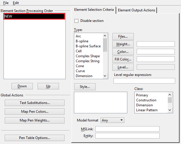
Step 5: Under the Element Selection Criteria button, specify which element type(s) you want to modify. For example, suppose you want to modify lines that have weight 1. Step 6: Under Type, select Line, and then click the Weight button and select 1 from the Select Weights dialog. Click OK to dismiss the Select Weights dialog. Step 7: Click the Element Output Actions tab. Specify the element output actions. For example, suppose you want lines with weight 1 to be printed in color with index value 1. Step 8: Set the Color check box and then type in an index value of 1 or click the color icon and select color 1. Step 9: Select File and Save. Modifying Pen TablesAll operations concerning pen tables can be carried out from the Modify Pen Table dialog. Sections present in the currently loaded pen table are listed in the Element Section Processing Order list box. It's File, and Edit menus can create and edit both new and existing pen tables. Using settings in the Element Selection Criteria tab of the Modify Pen Table dialog, you can define the parameters for selecting elements in the design file. Having set the selection criteria, you can use the Element Output Actions tab settings to define the changes required for the printed output. 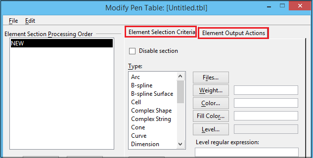
You can define an individual parameter for element selection and, based on that evaluation, specify modification of the identified element in the output file. Similarly, you can evaluate multiple parameters. However, when you specify more than one parameter, they are considered as a Boolean AND operation. Elements for which you specify multiple parameter values must meet all specified criteria before they are identified.
How to Edit a Pen TableYou should have a created pen table attached to the design file and then follow the following steps: Step 1: In the Print dialog, click on the Edit button. 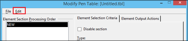
Step 2: The Modify Pen Table dialog opens. Note: If the configuration variable MS_PENTABLE_EDITOR is set to HIDE_MENU_ITEM, the Edit icon is removed from the Print dialog.Pen MapsPen maps differ from Element Selection Criteria and Element Output Action pen table resymbolization in that they operate on individual vectors instead of fundamental elements. This feature can be considered a user interface for color maps, with the data stored in the pen table instead of the .pltcfg file. Pen maps let you apply multiple output color and width symbology to different parts of the same element. For example, an element with a multi-colored custom line style or an associative hatch linkage definition with a different color may be assigned unique widths for the specific colors. This is not possible using element-based output actions. The order of resymbolization is as follows:
Next TopicThree properties of metals
|
 For Videos Join Our Youtube Channel: Join Now
Feedback
- Send your Feedback to [email protected]
Help Others, Please Share


