| |

What is PotentiometerThe Potentiometer refers to three-terminal variable resistors that have the resistance used to regulate the flow of current. With increasing temperature, a large amount of current is restricted due to the resistance of the Potentiometer, and only a small amount of current is allowed to pass through the circuit. With reducing the temperature, a larger current is passed through the circuit because the Potentiometer has low resistance. It is used to determine the EMF (Electromotive Force). It is also known as potmeter or pot. It is a type of passive variable resistor with a wire or carbon wound, with three terminals used to obtain desired voltage division. Therefore, its name is a variable voltage divider. How does the Potentiometer Work?As we know, the Potentiometer has a three-terminal and is used in different types of electric and electronic circuits. To know how does Potentiometer work, we use the resistance principle. The easiest procedure to divide the Voltage is to take a resistor (Wire-wound) and attach it with the sliding contact. The diagram below depicts the pot (Variable Voltage Divider) comprises a wire wound resistor with sliding contact. In the given figure, the sliding contact or rotating shaft is at position P. The resistance between terminal P and the rotating shaft is more like that for terminal Q and sliding contact. The Voltage between the rotating shaft and terminal Q is half. 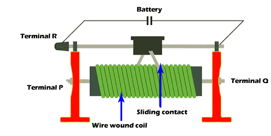
Let's consider an example, suppose a battery having total Voltage is 120 V, the voltage across the terminal Q and the rotating shaft is 30 V, and the Voltage between terminal P and rotating shaft is 80 V. If the rotating shaft is moving towards the terminal P, the resistance decreases. Now, the Voltage across terminal Q is more. Similarly, the Potentiometer divides the Voltage. The Potentiometer comprises a long resistive wire having length L and a battery of known EMF V. Consider a primary circuit arrangement with the two ends L connected by a battery terminal. The one end of the circuit is connected through the cell whose EMF is represented by E, which is to be determined. The other end of the circuit is connected to a galvanometer G. This circuit is considered a secondary circuit. 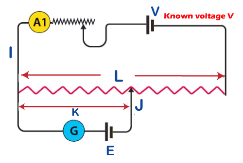
The working principle of the Potentiometer primarily depends upon the EMF of the circuit, which is directly proportional to the length of the wire that has a uniform cross-sectional area with a constant flow of current. Let's understand the working principle of the Potentiometer through the derivation. We know that, V = IR (Ohm's law) where, V = Voltage, I = Current, and R = Resistance. And 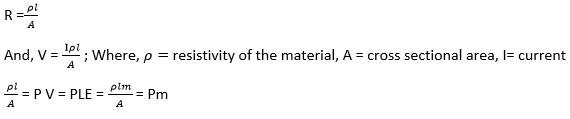
Where, m = length of potentiometer wire E = Lower EMF of the cell P = Constant The potential difference is zero, and there is no current flow, so the galvanometer has null detection. m is the length of the null point, and the unknown EMF can be found by knowing m and P 
Since the EMF has two different cells, let N1 is the first cell with EMF E1, and L2 is the second cell with EMF E2. Therefore, 
Types of PotentiometerThe Potentiometer is made up of various kinds of materials like carbon composition, metal film, conductive plastic, etc. Based on their work, the potentiometers are divided into three different types Rotary Potentiometer, Linear Potentiometer, and digital Potentiometer. The most popular kind of Potentiometer is Rotary type potentiometer. Rotary Potentiometer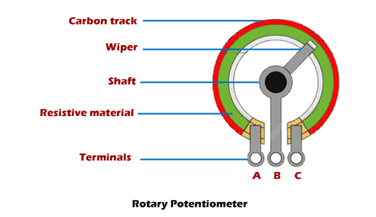
Potentiometers are primarily used for obtaining adjustable supply voltage to a part of electrical and electronic circuits. The Best example of a rotary potentiometer is the volume controller that we are using in day-to-day life in our music system, where the rotating knob is used to control the supply of the speaker. It gives adjustable supply voltage to the electronic and electrical circuits. Linear PotentiometerThe function of the Linear Potentiometer and rotary Potentiometer are similar to each other, but instead of a semi-circle resistance in the rotary Potentiometer, there will be a linear resistor here with the rotating shaft. The two ends of the linear resistor are connected across the input voltage source, and the output is taken between the rotating shaft and any one end of the linear resistor. With the help of a linear Potentiometer, it can measure the Voltage across the branch of a circuit. 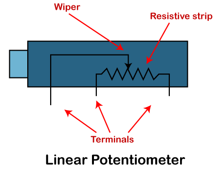
Digital PotentiometerThe Digital potentiometer, also known as Digi Pot, provides the most accurate measurement compared to mechanical potentiometers like rotary and linear Potentiometer. The digital Potentiometers are not impacted by any environmental changes like humidity, shocks, vibrations, etc. Digital Potentiometer provides high reliability and accuracy with very low power dissipation. M52429 from Renesas and MCP41010 from microchip is the most popular digital Potentiometer ICs. 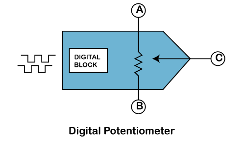
Application of PotentiometerAudio Control: The rotary potentiometer and Linear potentiometer are used to control the volume and other audio-related signals of audio devices. For Example, speakers, Mobile devices, radio, etc. Motion Control: In a circuit, it is used to create a closed-loop control. Potentiometers are also used as position feedback devices called servomechanism. Television: In television, it is used to regulate the image quality like brightness, color, contrast, etc. It is also used to regulate the audio of television. Transducers: Potentiometers give a huge output signal, so it is used to design a displacement transducer. Difference between Rheostat and PotentiometerRheostat refers to an instrument that is used to regulate a current by varying the resistance. The function of a rheostat is the same as a resistor except for the fact that the resistance can be varied; the primary part over the rheostat is a significant cause for the change in resistance, the length at which the contact is mounted decides the resistance offered by the rheostat. If you want to determine the desired current, you need to connect the power supply in series to the rheostat and an ammeter in series to the rheostat output; by moving the contact, you can see the amount of current displayed in the ammeter varying. When you get your desired current, you can leave the contact at that position. The Potentiometer refers to three-terminal variable resistors that have the resistance used to regulate the flow of current. With increasing temperature, a large amount of current is restricted due to the resistance of the Potentiometer, and only a small amount of current is allowed to pass through the circuit. With reducing the temperature, a larger amount of current is passed through the circuit because the Potentiometer has low resistance. Difference Between Rheostat and Potentiometer
Next TopicUser Interface Design
|
 For Videos Join Our Youtube Channel: Join Now
Feedback
- Send your Feedback to [email protected]
Help Others, Please Share


