Antenna
An antenna is a metallic structure that is used to transmit radio EM waves. We can define it as the launching of waves or radiations in space, which is efficiently accomplished with dielectric structures called antennas. An antenna acts as a transducer that converts the electrical power into EM waves. The electric charges are the source of the EM or electromagnetic waves.
The transmitting antenna carries the electric current, converts it into the form of radiation, and transmits it into space. The Antenna can be used as a transmitting antenna or the receiving antenna.
The antenna uses voltage and current from the source (transmission line) to launch Electromagnetic waves into the particular medium.
Here, we will discuss the following topics.
Types of Antenna
Radiation pattern of an Antenna
Effect of Ground on the Antenna
Regions of an Antenna
Parameters of the Antenna
Types of Antenna
The different types of Antenna are as follows:
Based on the directions
The antennas are categorized based on the direction of the radiations emitted by them. The three major types of Antenna based on the direction are Omni-directional antenna, semi-directional antenna, and directional antenna.
Let' discuss the above types of antenna in detail.
1. Omni-directional antenna
The Omni-directional antenna radiations radio power equally in all the directions. The power emitted is perpendicular to the axis. It further declines to zero towards the axis. It is commonly used in applications that require communication with multiple devices.
2. Semi-directional antenna
Semi-directional antennas also radiate the power in a particular direction providing the radiations across a large area. It is generally a point-to-point communication used for short-to medium distance communications.
3. Directional antenna
The directional antenna radiations power in a specific direction. The power radiated thus has a strong beam. It prevents the radiations from any interference due to the radiations in a particular direction. It has a narrow beam and double gain as compared to the Omi-directional antenna.
The application of directional antenna includes GPS (Global Positioning system), cellular networks, etc.
Wire Antennas
Wire Antennas are the type of radio antennas that consists of the long wire suspended over the ground. The wire acts as an antenna by picking up the signals and further radiating them.
The wire antennas are further categorized as:
1. Vertical Antenna
- The vertical antenna radiates the power in all directions It means that it radiates less power in upward or downward direction. It is used where the horizontal antenna is unable to provide the requirements.
- The shape of the vertical antenna is similar like a vertical rod mounted on the ground. The vertical antenna can also have a physical earth connection, where it is connected to the Earth using ground rods.
- The radiations emitted by the vertical antenna are similar to the Omni-directional antenna. It advantages include low angle of radiation, ease of mounting, windage, etc.
2. Loop Antenna
- The loop antenna consists of turns in a wire. The perimeter of the loop can be large or small, depending on the operating frequency.
- The loop can be in the shape of a square, rectangle, circle, or any geometrical shape but in the form of a closed loop. It is shown below:
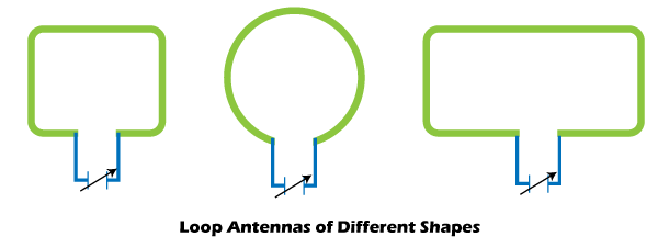
- The essential requirement of the large loop antennas is the loop's perimeter equal to the 110% of the one-full wavelength.
- Some antennas are shaped in the form of a loop but are not loops due to some breaks in between. For example, Halo Antenna. The Halo Antenna is bent in the form of the loop but has breaks in between. It can be considered as a dipole antenna. The break-in such antennas is analyzed as the air break or air capacitor.
- Small loop antennas are generally lossy. Hence, it is suitable for low-frequency transmissions below 10MHz. Its applications include AM (Amplitude Modulation) broadcast receivers, land mobile radio, etc.
3. Helical Antenna
- It consists of a wire in the form of a helix. The helical antennas can be directional or omnidirectional. The directional helical antennas are generally mounted on the ground plane.
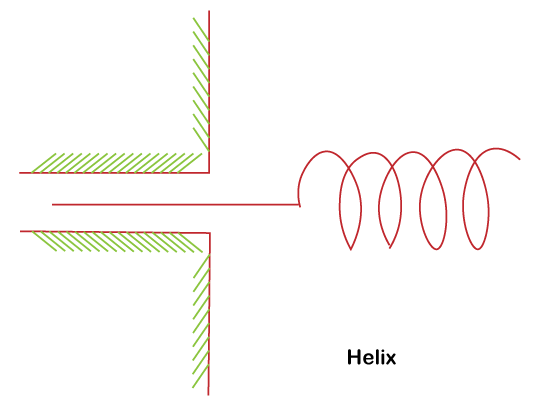
- The helix antennas can use operators in either normal mode or axial mode. The antenna's diameter and pitch in the case of the normal mode are smaller than the wavelength. It acts as a monopole antenna in such a case. The helix antenna operating in the normal mode is also called a broadside helical antenna.
- The antenna's diameter and pitch in the case of the axial mode are comparable to the wavelength. The antenna behaves as a directional antenna in the axial mode. The helix antenna operating in the axial mode is also called an end-fire helical antenna.
- The helix antenna can comprise of one, two, three, or four wires. A helix antenna with two wires is called a bifilar Similarly, a helix antenna with four wires is called a quadrifilar.
- The helix antenna behaves like an inductively loaded monopole due to the added inductance. The inductance is due to its helical shape. The monopole antennas can be used as the electrically short monopoles (antenna shorter than the signal wavelength).
Aperture Antennas
A common example of the Aperture Antenna is the Horn Antenna.
1. Horn Antenna
- It is shaped like a horn that directs the radio waves in the form of beam.
- The horn antennas are used at microwave and Ultra High Frequencies. The frequency range generally lies above 300MHz. The working of a horn antenna is similar to that of a musical instrument trumpet.
- The diagram of the horn antenna is shown below:
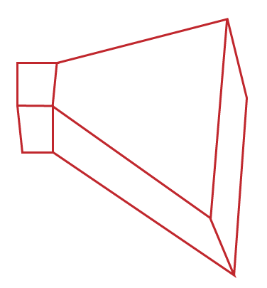
- The horn antenna allows the radiation of the wave energy with minimum reflection. The other types of horn antenna are ridged horn, exponential horn, conical horn, etc.
- The wavefronts of the horn antenna are spherical. The phase due to the spherical wavefronts increases smoothly from the edges towards the center.
- The increase in the size of the horn increases phase error. It further provides the horn antenna a wider radiation pattern.
- When the horn antenna is combined with the parabolic reflector, the antenna thus formed is called horn-reflector antenna.
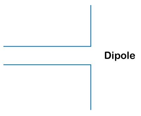
Dipole Antenna
- The Dipole antenna consists of two straight wires that lie along the same axis. It is also called a doublet. It is the most common used class of the antenna. The two wires or conductors of the dipole antenna are connected to the transmitter or receiver.
- Other variants of dipole antenna include turnstile antenna, halo antenna, batwing antenna, etc.
- The dipole antennas smaller than one half the wavelength is called as short dipole antennas. It has very low radiation resistance.
The dipole antenna is further categorized as half-wave dipole antenna, monopole antenna, Quarter-wave monopole antenna, and Hertzian dipole.
1. Half-wave Dipole Antenna
- As the name implies, the length of the half wave dipole antenna is half a wavelength. It is the most common used type of dipole antenna.
- The half-wave dipole's radiation pattern is zero around the axial direction and maximum perpendicular to the conductor.
- The half-wave dipole antenna is used in applications where full-wave dipole becomes large to use.
2. Monopole Antenna
- The monopole antenna consists of a single rod or conductor that is mounted on the ground plane or any other conductive surface. One side of the feedline (cable that connected the antenna with the transmitter or receiver) antenna is connected to the lower end of the dipole. The other end is connected to the ground that acts as the Earth for the antenna.
- The radiation pattern of the monopole antenna is also Omni-directional.
- A monopole antenna can be considered as vertical dipole antenna whose bottom half is replaced by a conducting plane. It is placed at right angles to the upper remaining half of the dipole, as shown below:
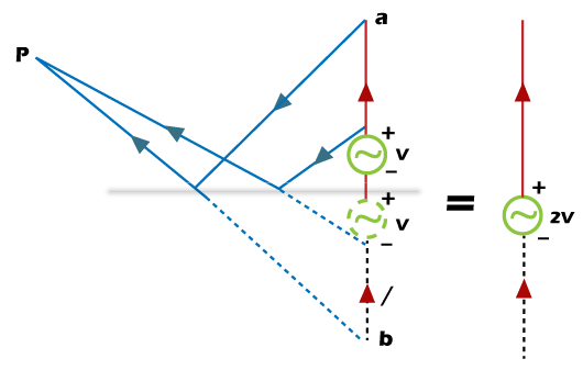
- The radio waves reaching the upper half of the antenna get reflected by the ground plane. The reflected waves thus form the missing part of the vertical dipole antenna. Hence, a monopole antenna is a perfect conducting antenna.
- The types of monopole antenna include umbrella antenna. The umbrella antenna is generally used as the transmitter at frequencies below 1MHz.
3. Quarter-Wave Monopole Antenna
- It is a type of monopole antenna.
- The antenna is generally one-quarter of the wavelength of the radio waves.
- The common types of Quarter wave monopole antenna are quarter wave whip antenna and quarter wave rubber ducky antenna.
- The quarter wave whip antenna consists of multiple rods or straight wire that radiates vertically and horizontally. It is also called a ground-plane antenna.
- The rubber ducky antenna wire in the form of a helix is sealed in a rubber jacket to protect the antenna. It is used in portable FM (Frequency Modulation) radios, walkie-talkies, etc.
4. Hertzian Dipole
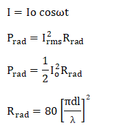
- Hertzian dipole carriers a uniform current, which is represented as:
I=Io cosωt
Hertzian dipole signifies the infinitesimal current element Idl, which serves as a building block for the field of the real antennas. The tiny current element practically is not possible but is considered as a reference for the practical antennas.
- The Hertzian dipole has a constant current over its short length along the conductor. Hence, it is used for the analysis of more complex geometrical antennas.
Radiation Pattern of an Antenna
The radiation pattern is also called as the antenna pattern. It is the three-dimensional plot of the radiations from the antenna at the far field. It means that the radiation pattern of an antenna is also known as a far-field pattern.
The square of the amplitude E is called a power pattern.
Where,
E is the voltage or field pattern when the amplitude of a particular field component is plotted.
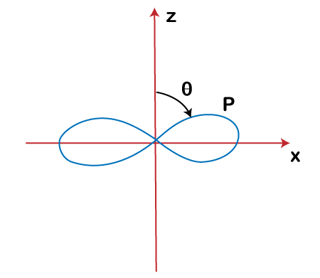
Let's consider the case of the Hertzian dipole.
The normalized E-plane pattern is shown below:
Similarly, its H-plane or Horizontal pattern is:
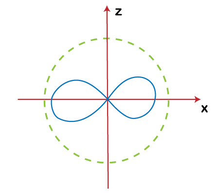
The H-plane pattern is the thee-plane pattern versus phi for a constant value of angle at 90 degrees. The component of the Hertzian dipole is a sine. Hence, the maximum value of the normalized E-plane is unity.
Characteristics
Let's discuss some characteristics of the radiation pattern of an antenna.
- The strength of the radio waves depends on the antenna source. The angular dependence of such radio waves in the field of antenna design is known as radiation pattern of an antenna. In other fields like lasers, optics, the pattern obtained is known as a near-field pattern.
- The near-field or Fresnel's pattern is generally defined over a plane is front of the source, while the far-field pattern is determined at the range of an antenna.
- The fundamental theory of the antenna is that the receiving pattern of the receiving antenna is similar to the far-field pattern of the antenna while transmission.
- The radiation pattern in some of the antennas is also called an interference pattern. It is because radiations from different parts can interfere at some angle.
- The Omni-directional antennas have a symmetric radiation pattern due to equal power radiated in all directions. These axial-symmetric antennas are monopole antennas, and dipole antennas.
Let's consider an example of a polar radiation plot. It consists of left and right lobes, as shown below:
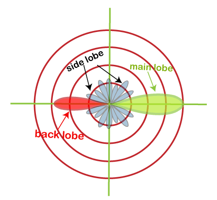
In the case of the directive antenna, the lobe in the direction of propagation is considered as the largest lobe. It is the main lobe of the radiation pattern so obtained. The other side lobes represent the radiations in an unwanted direction.
Effect of Ground on the Antenna
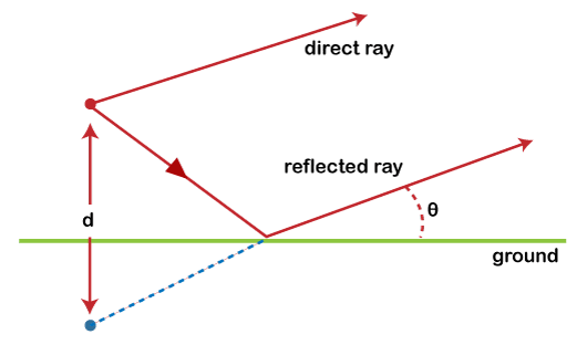
- The reflections from the ground are considered as the multipath for the radio waves. The ground plane for some of the types of antenna is important. In the case of a monopole antenna, the reflections from the ground work as a replacement of the lower half of the antenna.
- According to Fresnel's coefficient, half of the Electromagnetic waves striking the ground are reflected, while half of it is transmitted into the ground. If the ground is a good conductor, all of the EM waves might get reflected. Similarly, a lossy ground can absorb large amount of striking power.
- The ground behaves as a lossy dielectric medium for frequencies less than 30MHz. We can also consider it as the range for the low frequencies to high frequencies.
- The antenna can be horizontally polarized or vertically polarized. In the case of a horizontally polarized antenna, the large portion of energy from the antenna at the frequency range between 3 and 30MHz reflects the ground. It suffers from TIR or Total Internal Reflection. The reflected waves can either suppress or strengthen the direct wave with a reversed phase.
- The ground reflects the vertically polarized radiations in the case of high conducting surfaces. Otherwise, it is not well-reflected.
- The ground at frequencies above 30 MHz or Ultra High Frequencies becomes a poor reflector.
Regions of an antenna
There are three regions of an antenna, as shown in the below image:
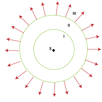
These three regions are numbered I, II, and III.
Let's discuss these three regions in detail.
Region I
It is called the oscillatory field region. It is generally close to the source (marked as S). It is the region within the 1/r^3.
Region II
It is called the near field region. It range lies between the 1/r^3 and 1/r^2.
Region III
It is called the far field region.
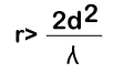
Region II is also called as Fresnel's field, while region III is called as Fraunhofer field. The distance between these two fields is:

Similarly, the boundary between these two regions can be calculated as:

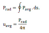
The equivalent radiation power is given by:
Where,
Rrad is the radiation resistance of the Hertzian dipole. The larger the value of the radiation resistance, the more power can be delivered to space. It means that we require antennas with large radiation resistance to deliver large amount of power to space.
For example,

Let the radiation resistance be 2 Ohms. It means that the antenna can deliver very small amount of power.
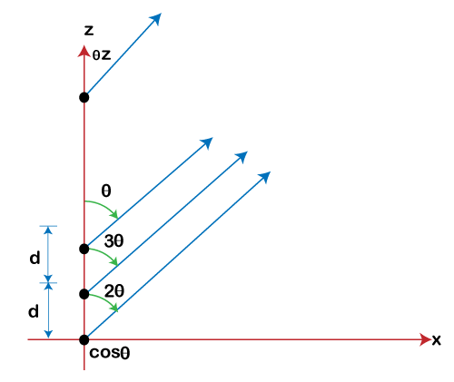
Antenna Arrays
The antenna arrays provide better directivity s compared to single antenna. It is a group of radiating elements that are arranged together to produce desired characteristics.
N-Element Array
The array factor of an antenna is given by:
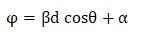
Where,
Alpha is the phase difference between the two consecutive array elements.
Antenna Parameters
The antenna parameters are used to determine the radiation intensity, gain, directivity, power gain, and efficiency of the antenna.
Radiation Intensity
The radiation intensity of the antenna is the integral of the average power. The unit of intensity is watts/ steradian. It can be represented as:
Power Gain
Let the input power and the radiation power of the antenna be Pin and Prad. The total input power can be represented as:
Pin = Pl + Prad
= 1/2 |Iin|^2 (Rl and Rrad)
Where,
Iin is the input current
Rrad is the radiation resistance
Rl is the ohmic resistance
Thus, the power gain of the antenna is given as:
Radiation Efficiency
The radiation intensity of the antenna is defined as the ratio of radiation power to the input power. We can say that radiation efficiency is the power gain ratio in a particular direction to the directive gain in the same direction.
It is given by:
Gp/Gd = Prad/Pin
Efficiency = Prad/ (Prad + Pl)
It means that the antenna's input power is the sum of the radiation power and the power loss.
Directivity
Directivity is also called as the maximum directive gain of an antenna.
It is given by:
D = Umax/ Uavg
Where,
Umax is the maximum radiation intensity
Uavg is the average radiation intensity
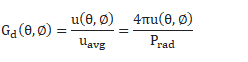
Gain
The Gain of an antenna defines the concentration of radiated power in a specific direction.
It is given by:
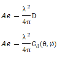
Effective Area
The effective area of an antenna is defined as the ratio of the average power received to the average power density. It is represented as:
Ae = Pr/ Pd
Where,
Ae is the effective Area
Pr is the average received power
Pd is the Power density
For a particular antenna, it is given by:
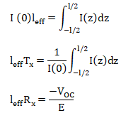
Effective length
The effective length of the antenna describes the effectiveness of the antenna. The effective length is similar to the equivalent length of the antenna. It radiates the same field strength as the actual antenna. The direction of radiations is perpendicular to its length.
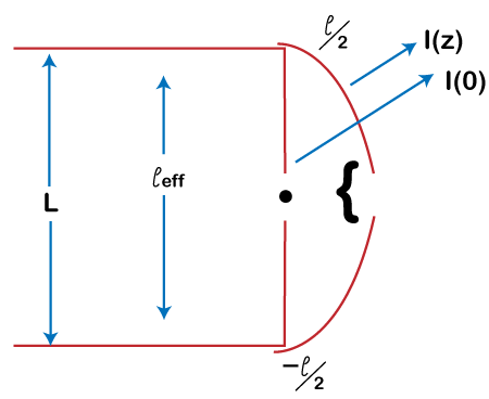
It is given by:
Friis Transmission Formula
The Friis transmission formula is used to relate the received power by the antenna to the power transmitted.
The receiving and transmitting antennas are separated by:
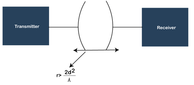
| 
 For Videos Join Our Youtube Channel: Join Now


