| |

CapacitorA capacitor is defined as the passive electronic device that stores the potential energy between its plates. The structure of the capacitor is as follows: 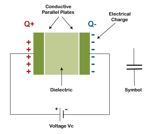
It consists of two plates with the dielectric or insulating layer between them. These plates are also called as electric conductors. Here, we will discuss the following topics:
Parts of a CapacitorThere are two parts of the capacitor called Conducting plates and dielectric. 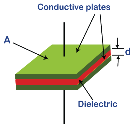
Let's discuss these parts of a capacitor in detail: Electric conductors or platesElectric conductors are the material that allows the electric current to pass through it. The common material for these conductors is metals. Electric current is defined as the flow of charge that is generated by the movement of electrons, holes, or charged ions. Electrons are negatively charged, while holes are positively charged. DielectricDielectric material between the plates acts as an electric insulator. The dielectric material of a capacitor can be polarized with the help of an electric field. The dielectric material stops the flow of charge when placed in an electric field. But, a slight shift in their equilibrium position can result in dielectric polarization. It is shown in the below diagram: 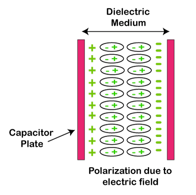
The positive charge and negative charge during dielectric polarization are displaced in opposite directions. For example, if a positive charge is displaced in the positive y-axis, the negative charge will be displaced in the negative y-axis. The common type of capacitor includes two electrical conductors with dielectrics between them. These conductors are in the form of metallic plates that can be a thin film, electrolyte, foil, etc. The dielectric materials are generally made of silica, mica, plastic film, oxide layers, glass, etc. How was the capacitor named? The capacitor was initially called as condenser. The term condenser is also in use today in large applications, such as automotive systems. In 1782, Alessandro Volta defined it as a device used to store a large amount of charge. The meaning of condenser started becoming unclear. It was further renamed as a capacitor, which was implemented in 1926. ApplicationsThe capacitors can be used for different tasks, such as filtering, bypassing, etc. It is also used in a variety of applications, such as:
Capacitors are used in applications that block DC (Direct Current) and permit AC (Alternating Current). Let's discuss the role of capacitors in different electrical networks, which are as follows:
The charge that a capacitor can hold is defined as capacitance. Let's have a look at the capacitors used in various applications. 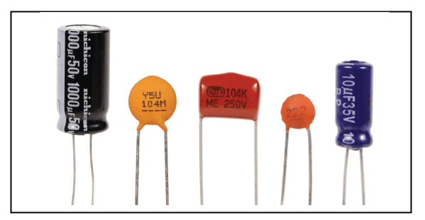
CapacitanceCapacitance is defined as the ratio of the charge on the conducting plates to the electrical potential. It is commonly termed as ideal capacitance. 
In practical cases, Capacitance is defined as the ratio of change in charge stored in a capacitor to the voltage or electrical potential change. The capacitance in practical cases is determined in terms of incremental changes. 
The SI unit of the capacitor is Farad. It is defined as the ratio of charge (positive or negative) on a conductor to the voltage between them. One Farad is defined as the one Coulomb of charge on a conductor that causes a volt voltage change. 1F = 1 Coulomb / 1 Volt Types of CapacitanceThere are two types of capacitance, which are listed below:
Self Capacitance It is defined as the required charge to be supplied to the conductor to increase the voltage or its electric potential by one unit. The self-capacitance of a conductor can be calculated using the formula: 
q = charge that the conductor holds V= voltage 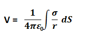
The self-capacitance of a conducting sphere can be calculated using the formula: 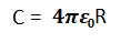
Where, R = radius of the sphere Mutual Capacitance Mutual capacitance, unlike self-capacitance, is defined based on both the plates of the capacitor. The mutual capacitance can be calculated using the formula: 
q = charge on the plates that can be + q and -q V= voltage between the plates of a capacitor 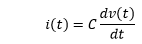
The current-voltage relationship can be written as: 
The energy stored in a capacitor can be calculated using the formula: Working of CapacitorA capacitor is considered a device with two conducting plates separated by the material between them. The material used is the insulating material called a dielectric. We can also use a vacuum as a dielectric material. We know, 
Where, Q = charge that the conducting plates hold V = Voltage or electric potential According to Coulomb's law, Two charged bodies exert at rest exerts an electric force between them called Coulomb force. It is also called an electrostatic force. Working: One conductor of a capacitor exerts a force on the particles that carry charge with the other conductor. It repels the same polarity charge and attracts the opposite polarity charges. Due to which, opposite charge particles will be present on the other conductor. So, both the surfaces of the conductor have equal and opposite charged particles. Hence, an electric field is developed. 
Flow of current in a Capacitor Let's connect the two terminals of a capacitor to the battery. The circuit of a capacitor connected with a battery is shown below: 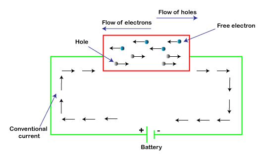
There are opposite charge particles present at the two surfaces of the conductor. These charged particles are called electron and holes. Holes have a positive charge, while electrons have a negative charge. When the battery is connected to the two terminals of a capacitor, electron and holes start moving, as shown above. Due to this, the current start flowing through a capacitor. The flow of current is always in the opposite direction to the flow of electrons. Let's discuss the simplest model of a capacitor called a Parallel Plate Capacitor. Parallel Plate CapacitorIt consists of two plates that are arranged in parallel, filled with the dielectric between them. The model of a parallel plate capacitor is similar to other practical capacitors. The dielectric should have uniform thickness without any spots. It is because the spots in the dielectric can cause capacitor failure. Let consider the area of plates: A The distance between the plates: d Let consider the electric field between the plates: E E will be constant due to the uniform distance between the two parallel conducting plates. If there is a positive charge on one plate, the other plate would have a negative charge. Let the charge be +Q and -Q on the two plates of the capacitor. The charge density of the capacitor is the ratio of charge to the area of the plates. The unit of charge density is coulombs per square meter. 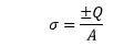
The magnitude of the electric field according to the Gauss law, can be calculated using the formula: E=σ⁄ε Thus, we can easily calculate the voltage between the plates. Voltage or V can be defined as the integral of the electric field from one conducting plate of a capacitor to another. 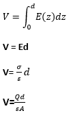
Let's calculate the capacitance of the parallel plate capacitor. We know, 
Substituting the value of V, we get: 
To achieve the highest capacitance, we need large permittivity, a small separation between the plates, and a large plate area. Sometimes, the charge is different on each plate. Let's calculate the voltage for such a case. 1. Let the charge on the first and second plates by Q1 and Q2. 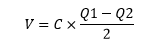
The plates of the capacitor in the above case are separated from other materials. 2. Let's connect the second plate of the capacitor to the ground, V = C x Q1 Energy Storage in a CapacitorWhen we move the charge from a negative plate to the positive plate, the capacitor's overall charge increases, for this, we require an external power source to move the charged particles from one plate to another. It is called work done. It is defined as the amount of work done required moving a charge from a negative plate to a positive plate against the opposite force of the electric field. Let's calculate the formula of energy storage in a capacitor. The voltage of a capacitor: V Amount of work done: dW Charge: dq The amount of work done in bringing the charge from negative to positive plate: dW = Vdq Total work done can be calculated as: 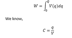
Putting the value of V from the above equation 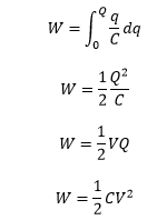
The energy in terms of Electric field Let's calculate the energy of a capacitor in terms of the electric field. 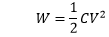
Putting the following values: 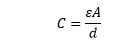
And E = V/d V = Ed We get, 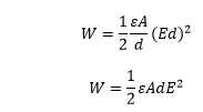
Current of a CapacitorThe current through a capacitor can be defined as the derivative of charge with respect to time. 
We know, 
Q(t) = CV Putting the value of Q(t) in the above equation, We get: 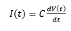
Now, The current through a capacitor can be defined as the capacitance multiplied by the derivate of the voltage with respect to time. Voltage of a CapacitorThe voltage across a capacitor can be defined as the ratio of the charge on the conducting plates to the amount of capacitance. 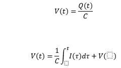
Where, Charge on the conducting plates of a capacitor is proportional to the integral of current and the voltage. Impedance of a CapacitorHere, we will calculate the impedance and reactance of a capacitor. The relation between impedance and reactance is: Z = -jX Where, Z is the Impedance X is the Reactance The Electric field generation causes impedance in a capacitor. 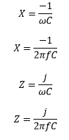
Where, ω: Angular frequency j: imaginary unit The magnitude of the impedance and reactance of an ideal capacitor is equal. 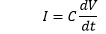
Let the voltage source be: V=Vo×cosωt Putting the value of V in the above equation: 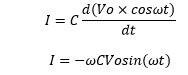
The capacitor has a peak current at sin(ωt)=-1 The capacitive reactance can be calculated as: 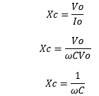
If, ω=∞, Xc=0 The capacitor passes high frequencies in such cases. If, ω=0, Xc=∞ The capacitor passes low frequencies in such cases. Let's consider the situation where the current leads by 90 degrees. I=-Iosin(ωt) I=Iocos(ωt+90) Capacitors Analysis in series and parallelLet's consider the circuit analysis of the capacitors connected in series and parallel. Capacitor connected in series Series circuits are often called as chain circuits. The voltage in a series circuit is the sum of individual voltages. V = V1 + V2 + V3 +… Vn Consider the circuit for the capacitor connected in series: 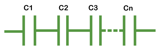
The total capacitance in series is the sum of the reciprocals of the capacitance of the connected capacitors, which is: ∑i1⁄C = 1/C1 + 1/C2 + 1/C3 + … 1/Cn Capacitor connected in parallel Parallel circuits have the same voltage across each component. The capacitance of the capacitors connected in parallel is added individually. Consider the circuit for the capacitor connected in parallel: 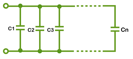
Laplace Analysis of CapacitorThe impedance of an ideal capacitor can be represented as: z(t) = 1/C z(t) = 1.1/C The Laplace transform of the above equation can be represented as: 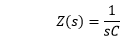
Where, C = capacitance of a capacitor S = complex frequency in s-domain Types of CapacitorsThere are two types of capacitors, Fixed and variable capacitors. Let's discuss the type of capacitors in detail: 1. Fixed CapacitorsThe fixed capacitors are the type of capacitors that gives fixed capacitance instead of variable. It means that the amount of charge provided by the fixed capacitors cannot be changed or adjusted. 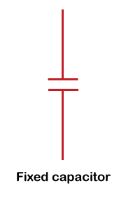
There are different types of fixed capacitors, which are listed below:
Polarized CapacitorsThe polarized capacitors have fixed polarity and can be inserted in only one way. It means the positive polarity of the circuit should be connected to the capacitor's positive terminal and negative polarity to the negative terminal. The incorrect connection can lead to permanent damage to the circuit. It may also damage the insulating oxide layer. 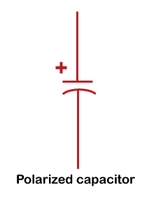
The polarity of these capacitors is clearly marked to avoid confusion while connecting. The common type of polarized capacitors is an electrolytic capacitor, which is discussed below:
Non-polarized CapacitorThe non-polarized capacitors do not have any negative or positive polarity and can be inserted randomly in any circuit. The film and ceramic capacitors are the common types of non-polarized capacitors. Let's discuss these two capacitors in detail.
Power film CapacitorsPower film capacitors are designed for high to very power applications, such as generators, medical equipments, power supplies, and induction heating. These capacitors come with a wide frequency range from 5000Hz to 1 MHz. The material and construction process of power film capacitors are similar to other types of capacitors. SupercapacitorsThe capacitors, such as Supercapacitors, pseudocapacitors, and EDLC (Electric Double-Layer Capacitors), come under the type of electrochemical capacitors. Supercapacitors are also known as ultracapacitors. These capacitors generally have high capacitance. The energy storage per unit mass or volume of Supercapacitors is 10 to 100 times more than electrolytic capacitors. These capacitors have better-charging capability, discharge, and charge cycles than rechargeable batteries. 2. Variable CapacitorThe amount of capacitance of the variable capacitors can be adjusted or changed. There are two types of variable capacitors, trimmer and tuning capacitors. The air is commonly used as a dielectric medium in such types of capacitors. The variable capacitors generally have a mechanical construction used to change the distance and surface area of the conducting plates. The symbol of the variable capacitor is shown below: 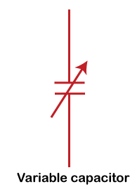
Next TopicDTE vs DCE
|
 For Videos Join Our Youtube Channel: Join Now
Feedback
- Send your Feedback to [email protected]
Help Others, Please Share


