| |

Beginner's Guide to Catia TutorialDassault Systemes, a global software corporation with its headquarters in France, created the CATIA programme. It is software that offers 3D design, computer-aided engineering solutions, PLM, and computer-aided manufacturing solutions, and is well known and widely used globally. The manufacturing industry and original equipment manufacturers are the major users of the programme (OEMs). New product management, analysis, and design are all aided by it. The effective model tool CATIA covers every step of the design to production process and blends 3D parametric features with 2D tools. Additionally, this tool offers isometric, detailed 2D drawings, or orthographic generation. Designing SoftwareDesigning software is widely accessible on the market, including CATIA, AutoCAD, Solidworks, Fusion 360, MATLAB, Ansys, and Creo. The most popular 3D design tool created by Dassault Systemes is the CATIA programme. CAD (Computer-Aided Design)Software for designing and analyzing models that have been developed based on geometrical characteristics is known as computer-aided design (CAD). On the computer screen, these models often appear as 3D models and 2D drawings. CAD software is used to boost output, improve design quality, and build databases for design manufacturing. Additionally, it has the power to improve collaboration by giving engineers and manufacturers access to a single source of truth. 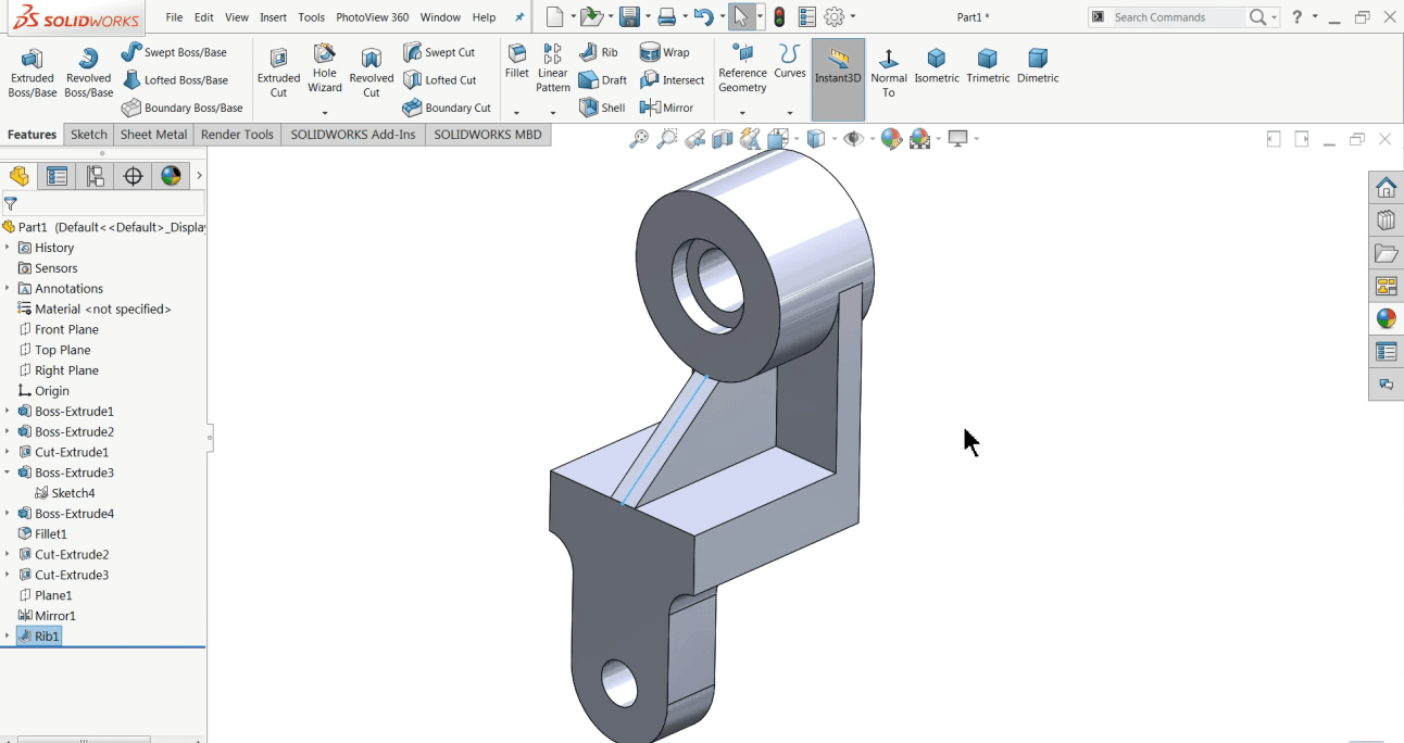
CAM (Computer-Aided Manufacturing)Utilizing software and Computer Numerical Control (CNC) equipment to automate the production process is known as Computer-Aided Manufacturing (CAM). Three essential elements of CAM are software, which creates a toolpath to create the final product, hardware, and software. Post-processing transforms a toolpath into a CNC language that the CNC machine can understand. Machinery turns raw materials into finished goods. 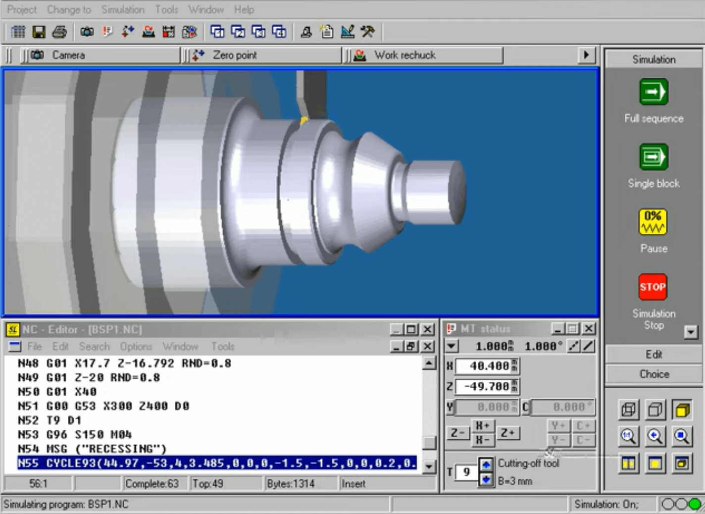
An example of CNC language is G-code, which is easily understood by CNC machines. The linear move G01 in this case uses the X1 and Y1 coordinates, the feed rate F10, the tool T01, and the spindle speed S200. CAE (Computer-Aided Engineering)An emerging discipline that advances CAD is computer-aided engineering (CAE). While CAE software offers a thorough technical study of models, CAD software assists in the creation of 2D and 3D models. It is used in engineering fields including fluid dynamics, kinematics, stress analysis, and finite element analysis, among others. CAE is frequently referred to as CAE tools and mostly employs CAD software. These instruments are used to evaluate the performance and resilience of parts and assemblies. 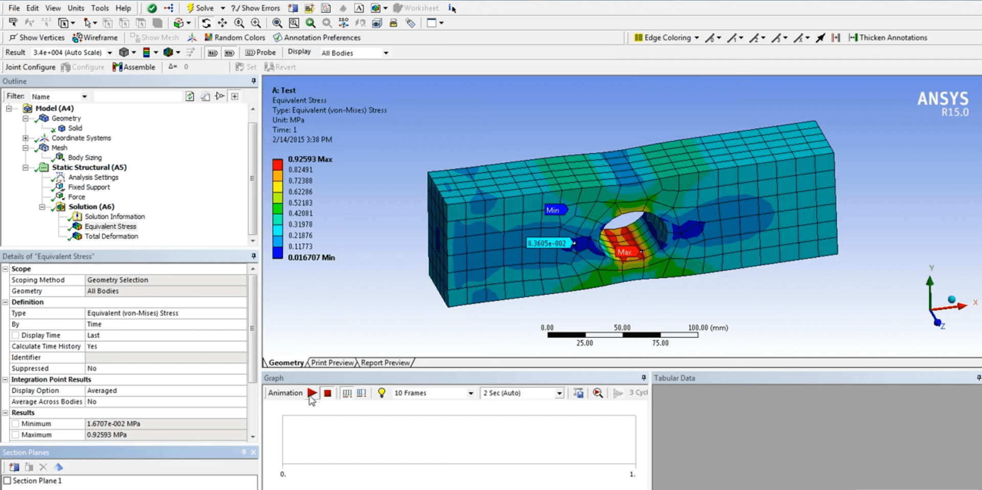
Describe CATIAThe most popular design tool from Dassault Systems is called CATIA, or Computer-Aided Three-Dimensional Interactive Application. It is a comprehensive software package that combines CAD, CAM, and CAE. CATIA offers solutions for product lifecycle management (PLM), 3D designs, CAE and CAM. The programme is frequently used by Original Equipment Manufacturers (OEMs) in the manufacturing sector to speed up the process of product design, analysis, and management. The 3D parametric characteristics of CATIA's solid model tool are combined with 2D tools, and it even covers the entire design-to-manufacturing process. Additionally, it offers an orthographic, isometric, auxiliary, and comprehensive 2D drawing. Therefore, this programme works best for manufacturing industries, mechanical engineers, system architects, and creative designers. CATIA 3D Experience:CATIA 3D Experience integrates Dassault systems and other brands like DELMIA, SIMULIA, etc. with ENOVIA to provide Product Data Management (PDM) and Product Lifecycle Management (PLM). 3D Experience is used to establish connections with different organizational divisions. It offers a user-friendly environment for all design and engineering tasks. These tasks are organized into groupings that can mirror actual processes, standardize iconography, enable a quick user learning curve, make it simple to locate the proper function, and increase productivity. About 50 jobs that support user experiences in design, fluid, electrical, and mechanical engineering, as well as systems engineering, are part of the 3D Experience CATIA portfolio. Attributes of CATIAIn a single working environment, CATIA provides the whole toolbox for engineering. Products with typical surface, drawing, and solids workbenches and a unified user interface are available for the electrical and composites design disciplines. The highlights of CATIA are as follows
CATIA versionsThe needs of the various businesses determine how software is developed. Without a doubt, every CAD software developer strives to create something new and improved. CATIA has been enhancing its versions continuously since 1980 to meet the need for design. Today, CATIA is one of the top tools for product invention and development across all business sectors. Let's examine its variations in more depth. V3 and V4 of CATIAThe initial version was released in or about 1982. The primary 3D CAD tool used by The Boeing Company is CATIA V3. Making 3D Designs requires the usage of CATIA V3. CATIA V3 was transferred from mainframe systems to UNIX later in 1988. Dassault Systems released and created CATIA V4 in 1993. The 3D digital mock-up and native formats including IGES, STEP, STL, and DXF have been supported since V4. .model (Part, Assemble),. session (Assembly of several model files),.exp,. dlv3, and. dlv4 are the file extensions used by CATIA V4. For convenience, Dassault Systems created a function that converts CATIA V4 files to CATIA V5. CATIA V5The most widely used and well-liked version of CATIA is V5. For both parametric and non-parametric modelling, V5 is a CAD programme. By adding new features like improved usability and expanded platform compatibility, CATIA V4 effectively replaces it. Without adding the SIMULIA and DELMIA packages, V5 is capable of doing fundamental FEA analysis and fundamental machining.
CATIA V6The 3D collaboration solution CATIA V6 is also known as CATIA 3D Experience. Users may define and execute the driving system to manage complexity and produce goods on schedule. It also allows users to model and assemble complicated products. Engineers can use it to aid in digital prototyping, which includes analysis and simulation for design and validation of function quality and performance throughout the design process. A real-time experience that forecasts performance in the actual world is made possible by CATIA V6's integration of complicated product behavior into the product description. To integrate the digital product experience, it incorporates the product definition's Shape, Architecture, Functional, and Engineering aspects. CAD softwareUsing CAD data formats, CATIA Composer enables users of all skill levels to produce high-quality 2D and 3D product outputs, such as technical documentation, interactive 3D experiences, technical drawings, etc. None of its output deliverables require any programming knowledge or other specific skills to generate them. The diverse CATIA applications that are at the foundation of Dassault Systems' solutions satisfy the needs of numerous sectors. These variations completely alter how businesses create, refine, and release new goods into the marketplace. What is CATIA used for?CATIA provides a tool for 3D design visualization. The main reasons people utilize it are its organized system, rendering technology, sketching, multi-platform development, active collaboration, market compliance, and technical insights. The automotive, defense, aerospace, and industrial equipment industries are among the ones that employ CATIA the most. A cross-discipline development platform and a multidisciplinary methodology have been incorporated by CATIA. It features an Unbreakable Relational Design and is based on Advance Surface Modelling. with incredible 3D workflows, social design environments, and user experiences. Even the design of electrical, electronic, and distributed systems benefits from it. In contrast to other 3D applications, the graphical user interface is also user-friendly. The workspace's tools and commands are all simple to use. The CATIA Workbench's featuresDifferent workbenches, or modules, are offered by CATIA. The following describes some of the most popular and significant workbenches and their purposes. The primary tool needed for solid modelling is Generative Shape Design Part Design. With an accessible and adaptable user interface, this workbench enables users to develop 3D mechanical components at any stage, from rough sketches to meticulous iterative designs. Let's look at a couple of the commands the Part Design workbench uses.
In this workbench, we can also examine the commands for part design. Assembly DesignThe assembly design workbench aids in shifting assemblies and assembling component pieces to create a basic framework. It is used to join together all the components to form a whole machine or component. We can even put the pieces together in this area to create a whole machine or building. Design of Generative ShapesUsers may develop an existing mechanical component design using wireframe and surface characteristics using the Generative Shape Design workbench. It offers a wide range of tools for creating and editing form designs. This enables employing surface and wireframe characteristics for both basic and complicated designs simple. Analysis of Generative StructureUsers can examine the first-order mechanical analysis for 3D systems using the generative structural analysis. It contains:
Design for Generative Sheet MetalFeature-based modelling is possible with sheet metal design. Concurrent engineering makes it easier to design, develop, and analyse sheet metal components in between unfolded or folded components. Kinematic ModelingUsers can connect a chain of joints that includes an assembly of parts, known as a mechanism, using kinematics. These joints specify the motion that the assembly is capable of. This workbench aids in the analysis of the structure's motion by explaining how a part or structure will move in the real world. Rendering in Real TimeUsers can set material specs that can be shared across the whole product development access using the Real-time Rendering workbench, which also maps materials to parts and products to produce realistic rendering. Bench for draftingUsers can generate drawings of 3D parts and build things using the Generative Drafting workbench. Benefits of utilizing CATIAThe advantages of using CATIA are as follows. Engineering knowledgeCATIA assists engineers in developing their understanding of the variables affecting the overall performance and quality of goods and their 3D modelling tools. Prototyping, in-depth analysis, and simulation enable users to conduct analysis and produce mechanical goods in the operational environment. A Multi-Platform ApproachDevelopers, engineers, and architects may use CATIA's multi-platform development to combine business processing, multi-discipline modelling, and verification. In order to better the simulation of complex systems and goods, it enables flexibility in integrating 3D processes and embedded systems. Drawing and rendering techniquesWith CATIA's ground-breaking 3D sketching features, users may create new designs and accept 2D sketches. Through flawless shadows, reflections, and global illuminations, users may produce high-quality renderings. Users and stakeholders are able to actively engage in the design process because to CATIA's collaborative 3D environment. It is reachable through 3D dashboards. Regulated systemWhen the pace of product design and development is delayed, CATIA's multidisciplinary approach is applied. It searches for specific criteria from several disciplines to aid businesses in developing and evaluating a new product. Market adherenceEngineers will remain compatible with market norms and standards thanks to CATIA, which lowers development costs for both products and systems. Cons of utilizing CATIAThese are the drawbacks of utilizing CATIA:
Next TopicWhat is CATIA Software
|
 For Videos Join Our Youtube Channel: Join Now
Feedback
- Send your Feedback to [email protected]
Help Others, Please Share


