| |

Use-Case ModelThe Use-case model is defined as a model which is used to show how users interact with the system in order to solve a problem. As such, the use case model defines the user's objective, the interactions between the system and the user, and the system's behavior required to meet these objectives. Various model elements are contained in use-case model, such as actors, use cases, and the association between them. We use a use-case diagram to graphically portray a subset of the model in order to make the communication simpler. There will regularly be a numerous use-case diagram which is related to the given model, each demonstrating a subset of the model components related to a specific purpose. A similar model component might be appearing on a few use-case diagrams; however, each use-case should be consistent. If, in order to handle the use-case model, tools are used then this consistency restriction is automated so that any variations to the component of the model (changing the name, for instance) will be reflected automatically on each use-case diagram, which shows that component. Packages may include a use-case model, which is used to organize the model to simplify the analysis, planning, navigation, communication, development and maintenance. Various use-case models are textual and the text captured in the use-case specifications, which are linked with the element of every use-case model. The flow of events of the use case is described with the help of these specifications. The use-case model acts as an integrated thread in the development of the entire system. The use-case model is used like the main specification of the system functional requirements as the basis for design and analysis, as the basis for user documentation, as the basis of defining test cases, and as an input to iteration planning. Origin of Use-CaseNowadays, use case modeling is frequently connected with UML, in spite of the fact that it has been presented before UML existed. Its short history is:
Components of Basic ModelThere are various components of the basic model:
ActorUsually, actors are people involved with the system defined on the basis of their roles. An actor can be anything such as human or another external system. Use CaseThe use case defines how actors use a system to accomplish a specific objective. The use cases are generally introduced by the user to meet the objectives of the activities and variants involved in the achievement of the goal. AssociationsAssociations are another component of the basic model. It is used to define the associations among actors and use cases they contribute in. This association is called communicates-association. Advanced Model ComponentsThere are various components of the advanced model:
SubjectThe subject component is used to represent the boundary of the system of interest. Use-Case PackageWe use the model component in order to structure the use case model to make simpler the analysis, planning, navigation, and communication. Suppose there are various actors or use cases. In that case, we can also use use-case packages in order to further structure the use-case model in much the similar way we use directories or folders to organize the information on our hard-disk. For various reasons, we divide the use-case model into the use-case packages, containing:
GeneralizationsGeneralizations mean the association between the actors in order to help re-use of common properties. DependenciesIn UML, various types of dependencies are defined between use cases. In particular, <<include>> and <<extend>>. We use <<include>> dependency to comprise shared behavior from an included use case into a base use case to use common behavior. We use <<extend>> dependency to include optional behavior from an extended use-case into an extended use case. How to Draw a Use-Case Diagram?If we want to draw a use case diagram in UML first, we must study the complete system appropriately. We need to find out every function which is offered by the system. When we find out all the system's functionalities then we convert these functionalities into a number of use cases, and we use these use-cases in the use case diagram. A use case means essential functionality of any working system. When we organize the use cases, then next we need to enlist the numerous actors or things that will collaborate with the system. These actors are used to implement the functionality of a system. Actors can be someone or something. It can likewise be a private system's entity. The actors should be pertinent to the functionality or a system in which the actors are interacting. When we enlist the use cases and actors, then next, we need to find the relationship of a specific actor with the system or a use case. An actor should find the total number of ways in order to cooperate with the system. One actor can interact with the numerous use cases simultaneously, or it may interact with the multiple-use cases concurrently. We have to follow the following rules while drawing use-case for any framework:
When to Use a Use-Case Diagram?The use-case diagram is an extraordinary system's functionality that is accomplished by a client. The objective of use-case diagram is to capture the system's key functionalities and visualize the interactions of different thinkings known as actors with the use case. It is the basic use of use-case diagram. With the help of the use-case diagram, we can characterize the system's main part and flow of work among them. In the use-case, the implementation of details is hidden from external use, and only the flow of the event is represented. Using use-case diagrams, we can detect the pre-and post-conditions after communication with the actor. We can determine these conditions using several test cases. Generally, the use-cases diagram is used for:
Use cases are planned to convey wanted functionality so that the exact scope of use case can differ based on the system and the purpose of making the UML model. Tips for Drawing a Use-Case DiagramThere are various tips for drawing a use-case diagram:
Importance of Use-Case DiagramUse Cases have been broadly used over the last few years. There are various benefits of the use-case diagram:
Basic Use-Case Diagram Symbols and NotationsThere are following use-case diagram symbols and notations: SystemWith the help of the rectangle, we can draw the boundaries of the system, which includes use-cases. We need to put the actors outside the system's boundaries. 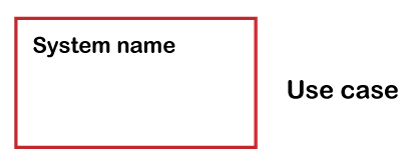
Use-CaseWith the help of the Ovals, we can draw the use-cases. With the verb we have to label the ovals in order to represent the functions of the system. 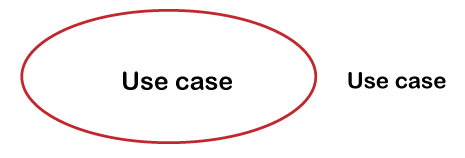
ActorsActors mean the system's users. If one system is the actor of the other system, then with the actor stereotype, we have to tag the actor system. 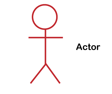
RelationshipsWith the simple line we can represent relationships between an actor and use cases. For relationships between use-case, we use arrows which are labeled either "extends" or "uses". The "extends" relationship shows the alternative options under the specific use case. The "uses" relationship shows that single use-case is required to accomplish a job. 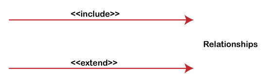
Guidelines for Better Use-CasesWith regards to examine the system's requirements, use-case diagrams are another one to one. Use-cases are simple to understand and visual. The following are some guidelines that help you to make better use cases that are appreciated by your customers and peers the same. Generally, the use-case diagram contains use-cases, relationships, and actors. Systems and boundaries may be included in the complex larger diagrams. We'll talk about the guidelines of the use-case diagram on the basis of the objects. Do not forget that these are the use case diagram's guidelines, not rules of the use-case diagram. Actors
Use-Cases
Systems/Packages
Relationships
Use-Case ExamplesUse-Case Example-Association LinkIn this use-case diagram, we show a group of use cases for a system which means the relationship among the use-cases and the actor. 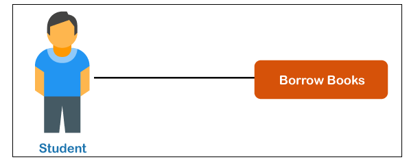
Use-Case Example-Include RelationshipIn order to add additional functionality that is not specified in the base use-case, we use to include relationship. We use it to comprise the general behavior from an included use case into a base case so that we can support the reuse general behavior. 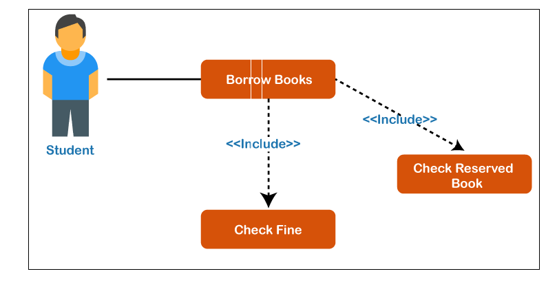
Use-Case Example-Extend RelationshipWith the help of the extend relationship, we can show the system behavior or optional functionality. We use <<extend>> relationship in order to comprise optional behavior from an extending use-case in an extended use-case. For example, the below diagram of the use-case displays an extend connector and an extension point "Search". 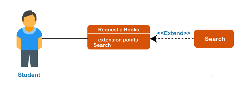
Use-Case Example-Generalization RelationshipIn the generalization relationship, the child use-case can inherit the meaning and behavior of the parent use-case. The child use-case is able to override and adds the parent's behavior. The below diagram is an example of generalization relationship in which two generalization connector is connected among three use-cases. 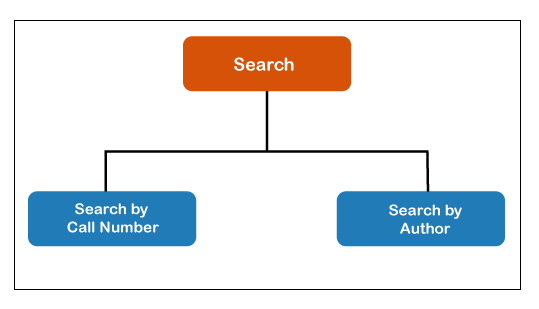
Use-Case Diagram-Vehicle Sales SystemsThe below diagram displays an instance of a use-case diagram for a vehicle system. As we can also see, a system as much as one vehicle sales system contains not in excess of 10 use-cases, and it is the delicacy of use-case modeling. 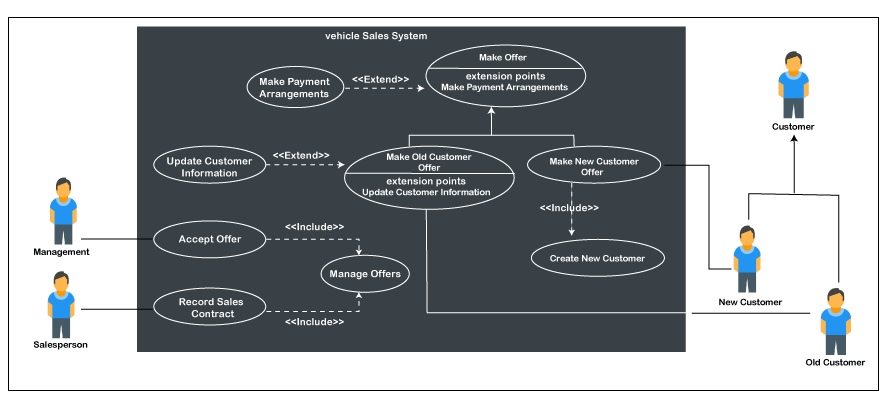
The use of include and extend is also displayed by the use-case model. In addition, there are associations that link between the use-case and actors. Use-Case Diagram-Student Management SystemThe below figure shows the working of the student management system: 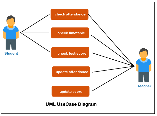
In the above use-case diagram of the student management system, we have two actors and five use-cases. The name of the actors is Student and Teacher. The use-cases represent the definite functionality of the student management system. Every actor interacts with a specific use-case. The student actor is able to check the test marks, time-table and attendance. These are only 3 interactions that can be performed by the student actor; however various use-cases are also remaining in the system. It is not must that every actor has to interact with each and every use-case, but it can happen. In the diagram, the name of the second actor is a Teacher. Teacher is an actor that is able to interact with all the system's functionalities. The teacher actor is also able to update the student's marks as well as attendance. Theses interactions of student as well as teacher actors together summarize the whole student management application.
Next Topic3D Printer
|
 For Videos Join Our Youtube Channel: Join Now
Feedback
- Send your Feedback to [email protected]
Help Others, Please Share


