| |

What is Microcontroller?A microcomputer made on a single semiconductor chip is called single-chip microcomputer. Since, single chip microcomputers are generally used in control applications, they are also called microcontrollers. Microcontroller contains all essential components of a microcomputer such as CPU, RAM, ROM/EPROM, I/O lines etc. Some single chip microcontrollers contain devices to perform specific functions such as DMA channels, A/D converter, serial port, pulse width modulation, etc. 8051 ArchitectureIn 1980, Intel introduced a powerful 8051 series of 8 -bit microcontrollers. They are the second generation of 8-bit microcontrollers. The 8051 microcontrollers are used for a variety of applications involving limited calculations and relatively some control strategies. They are used for industrial and commercial control applications, appliances control, instrumentation etc. The 8051 contains Boolean processor, full duplex serial port and power saving circuitry in addition to essential components such as 8-bit CPU, RAM, ROM/EPROM/OTPROM, timer/counter and parallel I/O lines. The following figure shows the block diagram or architecture of Intel 8051 microcontroller. 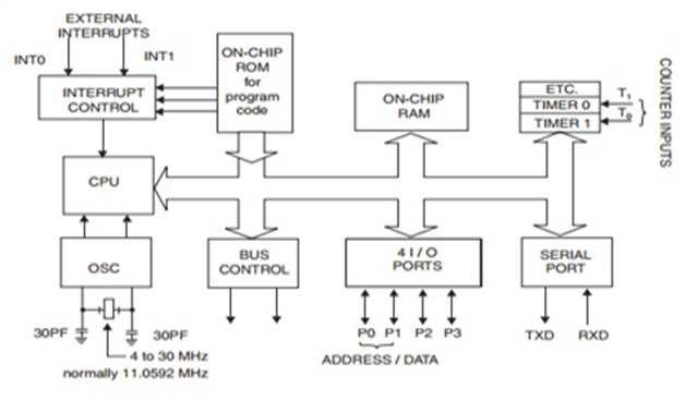
8051 Pins Description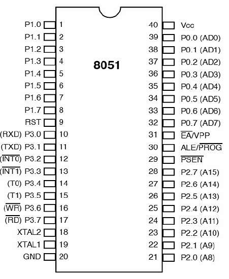
The pin diagram of 8051 microcontroller consists of 40 pins as given below: Pin 1-8 (Port1): These are 8-bit bidirectional I/O port with internal pull-up resisters. It does not perform any task; it is just an I/O port Pin 9 (RST): It is a Reset input pin which is used to reset the microcontroller to its initial position. Pin 10 to 17 (Port 3): It is also an 8-bit bidirectional I/O port with internal pull-up resisters. Additionally, it performs some special functions:
Pin 18 and 19: It is XTAL1 and XTAL1 pins respectively. These pins are used for connecting an external crystal to get the system clock. Pin 20 (GND): It is a ground pin. It provides the power supply to the circuit. Pin 21 to 28 (Port 2): These pins are bidirectional I/O port. Higher order address bus signals are multiplexed with this bidirectional port. Pin 29 (PSEN): It is a Program Enable Pin. Using this PSEN pin external program memory can be read. Pin 30 (ALE/PROG): This pin is the Address Latch Enable pin. Using this pin, external address can be separated from data. Pin 31 (EA/VPP): Named as external Access Enable Pin (EA). It is used to enable or disable the external memory interfacing. Pin 32 - 39 (Port 0): These are also a bidirectional I/O pins but without any internal pull-ups. Hence, it requires external pins in order to use port 0 pins as I/O port. Lower order data and address bus signals are multiplexed with this port. Pin 40 (VCC): This pin is used to supply power to the circuit. 8051 I/O ports8051 microcontroller have 4 I/O ports each of 8-bit, which can be configured as input or output. Hence, total 32 I/O pins allows the microcontroller to be connected with the peripheral devices. Note: Pin can be configured as 0 for output and 1 for the input.1) PORT 0P0 can be used as a bidirectional I/O port or it can be used for address/data connected for accessing external memory. When control is 1 the port is used for address or data interfacing. When the control is 0 then the port can be used as a bidirectional I/O port. 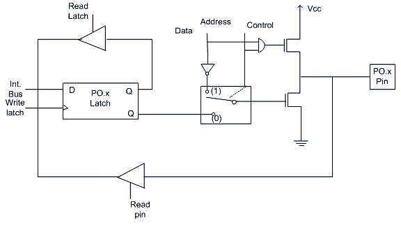
Fig: Structure of port 0 pin PORT 0 as an Input Port If the control is 0 then the port is used as an input port and 1 is written to the latch. In this type of situation both the output MOSFETs are off. Since the output pin has floats therefore, whatever data written on pin is directly read by read pin. PORT 0 as an Output Port If we want to write 1 on pin of P0, a '1' written to the latch which turns 'off' the lower FET while due to '0' control signal upper FET also turns off. Suppose we want to write '0' on pin of port 0, when '0' is written to the latch, the pin is pulled down by the lower FET. Hence the output becomes zero. 2) PORT 1PORT 1 is dedicated only for I/O interfacing. When used as an output port, not needed to connect additional pull-up resistor like port 0. To use PORT 1 as an input port '1' has to be written to the latch. In this mode 1 is written to the pin by the external device then it read fine. 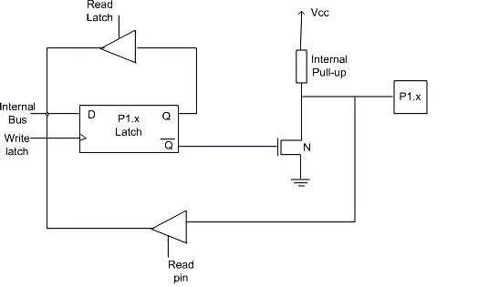
Fig: Structure of port 1 pin 3) PORT 2PORT 2 is used for higher external address byte or a normal I/O port. Here, the I/O operation is similar to PORT 1. Latch of PORT 2 remains stable when Port 2 pin are used for external memory access. 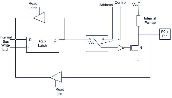
Fig: Structure of port 2 pin 4) PORT 3Following are the alternate functions of PORT 3:
It works as an I/O port same like port 2. Alternate functions of port 3 makes its architecture different than other ports. 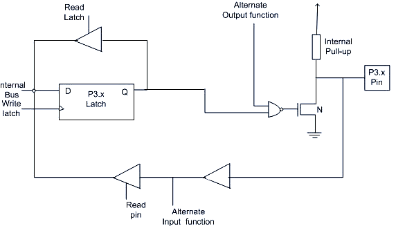
Fig: Structure of port 3 pin 8051 interruptsInterrupt is a process of creating a temporary halt main program and pass the control to the external sources and execute their task and then passes the control to the main program where it held left off. 8051 has 5 interrupt signals, i.e.
The number of interrupt sources differs from version to version. It varies from 5 to 15. The important interrupt sources are: one from the serial port, two from timers, two from external interrupts INT0 and INT1. Each of the interrupts can individually be enabled/disabled by setting/clearing a bit in the special function register IE (interrupt enable). The IE register also contains a global disable bit, which disables all the interrupts. Each interrupt can also be programmed to one of the priority level scheme by setting/clearing bits in the special function register IP (Interrupt Priority register). A low priority interrupt can be interrupted by a high priority interrupt, but it cannot be interrupted by another low priority interrupt. A high priority interrupt can?t be interrupted by a low priority interrupt. Difference between Microprocessor and Microcontroller
Next TopicPeripheral Devices
|
 For Videos Join Our Youtube Channel: Join Now
Feedback
- Send your Feedback to [email protected]
Help Others, Please Share


