| |

Embedded System Project: Fire Detection and Control SystemFire Sense using 8051 Microcontroller and Flame SensorTo avoid all the problems mentioned about the current fire fighting system and to have a better and reliable security system against fire accidents. There is used fire sensor which senses fire. If fire start, motor turn ON. If there is not firing, motor is turn OFF. REQUIREMENTS:
Aim of the ProjectOur aim is to design such project that sense fire. When there will be firing, motor will turn ON and water is start otherwise motor will be turn OFF. In places where such systems were installed it was seldom observed that they posed more problems than solutions. For example, many times the sprinklers went off because of the smoke caused by some harmless reason thereby creating a lot of mess and nuisance even when there was no fire. Thus a problem of false alarm was there. Not only this, in places like offices, museums, etc. sometimes when a small fire broke out, the damage caused by the water sprinklers, by spoiling the important paperwork, electronic items or pieces of art and history, was more than what the fire could have caused. Block DiagramConsider the block diagram of fire sensing circuit using microcontroller and flame sensor as key component is:- 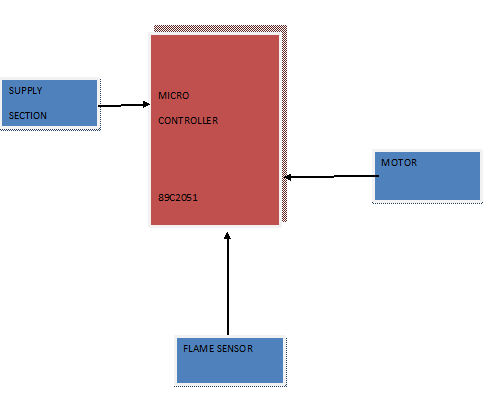
Working of the ProjectThis project comprises microcontroller one is for decision making. Fire sensor is for sensing fire. There is used fire sensor which senses fire. If fire start, motor turn ON. If there is not firing, motor is turn OFF. In this project we use 89c2051. Circuit Diagram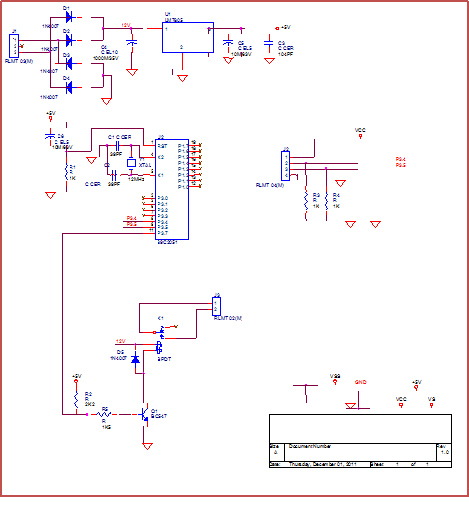
Circuit DescriptionPOWER SUPPLY SECTION:
Microcontroller Section
Source Code:
Next TopicRFID Based Attendance System Project
|
 For Videos Join Our Youtube Channel: Join Now
Feedback
- Send your Feedback to [email protected]
Help Others, Please Share


