| |

Useful Tips for New NX UsersHave you recently made the conversion from another CAD programme to NX? We will provide helpful advice in this blog for any CAD users who could be switching to Siemens NX for the first time. We will discuss the following subjects:
1. The Command Finder: The NX user interface's upper right search window is called the Command Finder. 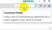
You may use this search bar to locate commands that you want to use or that you might not be aware of. The Command Finder will show you exactly where the command is located in the Menu once you've chosen the one you want to use. 2. NX Help (F1): Finding reliable "How to" NX tutorials and material online might be challenging. The "On Context Help (F1)" function in the NX programme is a fantastic tool that will let you access these resources. Simply tapping the F1 key will bring up this utility. The Siemens NX Help website will then be sent to you, where you may do a custom search for any relevant material. Then, a results page with reliable information pertinent to your search will be presented. 3. Hot Keys: By being familiar with the following NX hotkeys, users of NX can operate more quickly, effectively, and accurately. The following shortcuts or hotkeys will be discussed: F8, CTRL F, Home/Windows Key, and CTRL F2. F8: Pressing this key will move the part's view to the orthogonal plane that is closest to it. CTRL F: To fit the perspective of your screen if you find yourself in a disorienting view of the part, press this key. Press the Home key, often known as the Windows key, to quickly see a trimetric view of your component. CTRL F2: Rotation difficulties may arise if you're using a 3D mouse or space navigation device. You may select a new rotation point by pressing CTRL + F2. The rotation will now change to reflect the new point that was given. Every part of assemblies has a.prt file extension at the end. No differences shall be made between drawings, assemblies, or component parts. This is a feature exclusive to Siemens NX. You probably don't need much of a model layout for an angle bracket to hold a number of components in relation to one another. Sketch, extrude, punch a few holes, and ensure that it fits before concluding... But before beginning in CAD, the design of a model layout may be quite beneficial for a core section where several components link to it. Make any essential prior decisions on drawings, expressions, part functions, installation needs, upcoming part servicing, etc. Predict how the component could change in the future and be ready for it by incorporating that change into your model design and, eventually, your CAD model. You can't plan for everything; therefore, experience is essential. Consider previous, comparable designs as well as any concerns gathered from production and servicing. You, your coworkers, and your clients will be grateful for it in two years when a modification is required. Although they have their uses, primitive objects like blocks, cones, cylinders, and spheres should typically be avoided. A sketch portion, open or closed, that is extruded or revolved for prismatic forms is where normal NX CAD workflow begins. For more organic or freeform designs, sweeping, lofting, and sweeping along guide curves are all available. Here are a few simple ideas to have in mind when you're sketching:
Create standard mathematical formulae or conditional formulas using expressions to define your NX component. In NX, expression lists are practically being used without your knowledge because they are produced in the background for every value that is entered in Utilize the tools at your disposal while making geometry on the fly. No matter how your design evolves in the future, this maintains your design purpose. Examples A and B show geometric constraints, Example C uses dimensional constraints driven by expressions, and Example D shows a poorly communicated design purpose.
Next Topic#
|
 For Videos Join Our Youtube Channel: Join Now
Feedback
- Send your Feedback to [email protected]
Help Others, Please Share


