| |

Electronic OscillatorsThe oscillator is an electronic device capable of producing electronic oscillations the form of signal waves, popularly sine waves, and square waves. Oscillations refer to the forward and backward movement. It also converts one form of a power supply to another. For example, DC (Direct Current) to AC (Alternating Current) The AC signal is generally in the form of a sinusoidal wave. It is because the variations produced by the rotor in the AC generator are similar to the variations of the sinusoidal signal. Oscillators are widely used in electronic devices, such as sequential circuits, clock generators, radio transmitters, quartz clocks, and video games. A device that converts AC to DC is commonly known as converter. But, after the invention of diodes and rectifiers, the oscillators can also convert DC to AC. The device that converts DC to AC is known as inverter. Thus, we can say that converts work oppositely as inverters. The types of oscillators are Wien bridge oscillator, LC oscillator, Crystal oscillator, etc. Among these types, crystal oscillators are also called as modern oscillators operating in the high frequency range. History of electronic oscillators
Oscillating frequenciesThe frequency at the output of the oscillator is measured in Hertz (Hz). It is defined as the cycles per second. The different type of oscillators generates a different range of frequencies. For example, LC Oscillators - High-frequency signals RC Oscillator - Low-frequency signals The main types of oscillators operating at different frequencies are RF (radio-frequency), audio, and low-frequency oscillators.
Let's discuss the types of electronic waveforms produced by the oscillators. Electronic WaveformsThe waveforms produced by the oscillators are sinusoidal, triangular, square, and sawtooth. All these waveforms can operate in various ranges, such as [0. 1], [-1, 1], etc. The sinusoidal curve defines the smooth continuous wave. It depicts the natural representation of various processes and their states. 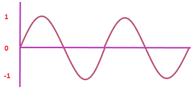
The square waveform has fixed amplitude and length. 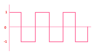
The triangular waveform reaches its peak at fixed points. It is known for its triangular shape. 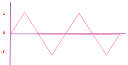
The sawtooth waveform represents the deflections in the form of teeth. A single sawtooth wave is known as ramp function wave. The wave rises upwards and sharply drops and again rises upwards. 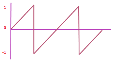
Types of OscillatorsThere are two types of oscillators, linear and non-linear. Linear OscillatorsThe linear oscillator produces sinusoidal waves at the output. It is also known as harmonic oscillator. The linear oscillators are further categorized as feedback oscillators and negative resistance oscillators. 1. Feedback oscillatorsThe examples of feedback oscillators include op-amps (operational amplifiers) and transistors. These devices are connected in a feedback loop with the output connected back to the input through a selective electronic filter. It provides a positive feedback to the connection circuit. When the power of the amplifiers or transistors is switched ON, the noise travels along with the current. When the noise travels through the loop, it gets amplified and filtered very quickly. The process goes on till the device gets the desired output, which becomes a sine wave at a single frequency. The positive feedback in oscillators has various advantages, such as sustained oscillations, stability, and cost effectiveness. Some of the oscillator uses selective frequency in their feedback loop, which is discussed as follows:
2. Negative resistance oscillatorsThe feedback oscillators generally used two-port elements, such as transistors and amplifiers. The linear oscillators can also use the one port networks with negative resistance. Examples of such devices are Gunn diodes and magnetron tubes. The negative resistance oscillators operate well at high frequencies. It can also amplify and increase the power of the signal. The feedback oscillators at high frequencies fail to produce the desires results. The block diagram of the negative resistance oscillator is shown below: 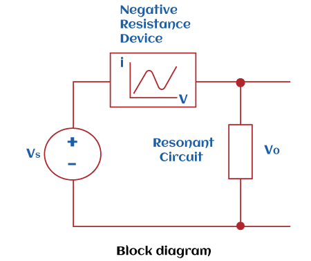
Non-linear oscillatorsThe linear oscillator produces non-sinusoidal (square, triangular, etc.) waves at the output. It is also known as a relaxation oscillator. It consists of a non-linear switching device, such as Schmitt trigger and the energy storage elements (L or C). Both the devices are connected in the feedback loop of the oscillator. The function of the switching devices is to switch the energy storage level of the connected devices periodically. It further changes the output waveform. Non-linear oscillators are used: VCO (Voltage Controlled Oscillators), ADC (Analog to Digital Converters), function generators, etc. The non-sinusoidal oscillators with their preferred operating devices are listed as follows: Square wave oscillator - Timers and counters Triangular wave oscillator - CRT (Cathode Ray Tubes), VCO, and oscilloscopes Sawtooth wave oscillator - Switch mode power supplies Requirements for oscillationsThe simple oscillator with the negative feedback is shown below: 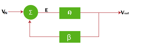
Where, VI is the input voltage Vo is the output voltage A is the amplifier B is the feedback factor of the negative feedback E is the error term E is equal to the summation of the input voltage and the feedback factor E = B + VI We can also represent error term as E = Vo/A The feedback is fed back to the summation junction at the input. The use of positive and negative feedback in the oscillators improves its performance. The negative feedback reduces the distortion and gain of the amplifier. The output voltage can be expressed as: Vo = E x A E = VI - BVo Putting E = Vo/A Vo/A = VI - BVo Vo/A + BVo = VI VI = Vo (1/A + B) Thus, the feedback expression of the feedback oscillator is: Vo/VI = A/(1 + AB) The oscillators do not depend on the external signals as the input. Instead, it uses a fraction of the output through the feedback as the input signal. The above system becomes unstable, when 1 + AB = 0 Or AB = -1 It is defined as the Barkhausen criteria. The negative sign indicates a phase shift of 180 degrees. If the term is positive, the phase shift is zero degrees. Voltage Controlled Oscillators
Next TopicRC Phase shift oscillator
|
 For Videos Join Our Youtube Channel: Join Now
Feedback
- Send your Feedback to [email protected]
Help Others, Please Share


