| |

Armature Reaction in DC GeneratorDC GeneratorA DC generator is a device that converts mechanical energy into DC electrical power via electromagnetic induction. An electromagnetic field (EMF) is produced in a conductor whenever the magnetic flux connecting it changes, which is how a DC generator works. Both the field and armature windings are present in a DC generator. The alternating EMF produced in a DC generator's armature winding is transformed into direct voltage by a commutator that is mounted on the generator shaft. While the field winding of a DC generator is mounted on the stator, the armature winding is mounted on the rotor. Working of a DC GeneratorAs seen in the below picture, a single turn loop 'ABCD' in a single loop DC generator rotates clockwise in a consistent magnetic field at a constant speed. The magnetic flux connecting the coil sides "AB" and "CD" continually varies as the loop revolves. The electromotive Force in one coil side is added to the electromotive Force in the other as a result of the change in flux linkage. 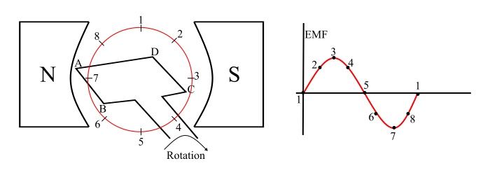
The following describes how EMF is produced by a DC generator:
It is obvious that the loop's produced EMF is an alternating one. This is such that any coil side, like AB, has EMF in one way when affected by N-pole while in the other way when affected by S-pole. As a result, an alternating current can flow through with a load when it is linked across the generator's terminals. This alternating emf produced in the loop may now be changed into direct voltage by utilizing a commutator. Armature ReactionThe term "armature flux" refers to the magnetic field created by the current flowing through the armature conductors. This armature flux distorts and reduces the magnetic flux produced by the primary poles. This interaction between the armature flux and the main flux is referred to as armature response. 1. Case1:-Think about a two-pole generator that is idle. Thus, there is no current flowing through the armature conductors. Only the major flux (φm), which is generated by the main poles, is present in the machine in this situation. The distribution of this primary flow with respect to the polar axis is symmetrical (i.e. center line of field poles). 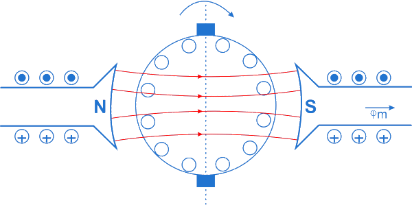
The magnetic neutral axis (MNA), which is a plane perpendicular to the flux axis, coincides with the geometrical neutral axis. The MNA is also known as the axis of commutation since the brushes are always positioned along it. 2. Case2:Consider an armature that is operating with no current flowing through the field coils. To determine the direction of flux produced by the current flowing through the armature conductors, use the cork-screw rule. Referring to the illustration, current flows into the paper plane through the conductors beneath the N-pole. As a result, the conductors beneath the N-pole are producing a downward flux. 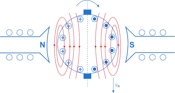
Comparably, the conductors under the S-pole transport current away from the paper's surface. Additionally, a downward-directed flux is produced by these conductors. As a result, a downward flux is produced via the armature by the whole armature conductor. Armature flux (φA) is the name given to this flux. 3. Case3:-In this instance, the simultaneous action of the armature and field currents is demonstrated. As a result, the machine has two fluxes inside it, one created by the generator's main field poles and the other by the current flowing through the armature conductors. The resultant flux (φR) is created by combining these two fluxes. 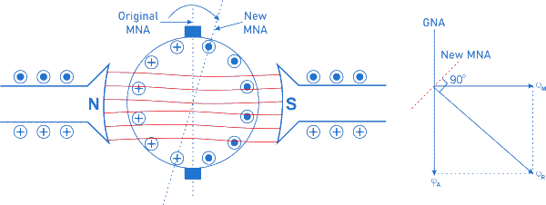
The principal flux hitting the armature is shown to be displaced and twisted from the explanation above. The distortion causes an increase in flux density at both the lower pole tip of the S-pole and the higher pole tip of the N-pole. At the lower pole tip of the N-pole and the higher pole tip of the S-pole, the flux density is also declining. As a result, the path of the resulting flux has changed to coincide with the generator's rotational direction. The MNA is also displaced since it is always perpendicular to the axis of the resulting flux. The rise in flux in one pole tip is less than the reduction in flux in the other pole tip because of the non-linear behavior and saturation of the core. The major flow is thus reduced. When a result, as the load increases, the produced emf (Eg ∝ Nφm) decreases. Armature reaction effectsThe armature reaction in a DC generator results in the following detrimental effects.
The Armature Reaction Effect: SolutionsThe armature response issue may be minimized using different techniques. 1. Position the brush differently-Using this technique, turn the brush mechanism until it is positioned correctly in the neutral zone. Only current with a fixed load can be used for this. 2. The poles' ends should be changed-In this procedure, the field pole tip must be altered so that the high reluctance channel prevents high flux from occurring on the ends. 3. Interpoles-The impact of armature response can be reduced by sandwiching a series of interpoles or commutating poles between the DC generator's main poles. The interpole's polarity must match that of the main pole directly to its left in the rotational direction. In order for the associated fluxes to fluctuate together with the load current, the interpole windings and armature are connected in series. 4. Compensating WindingThe armature reaction varies dramatically as a result of the heavy load activities. The armature flux in these generators is not sufficiently neutralized by the interpoles. Therefore, compensatory windings are employed to solve this issue. An auxiliary winding that is inserted into the slots of the main poles is the compensating winding. The compensatory winding and armature are linked in series such that the current flowing through any given pole face of the compensating conductors will be flowing in the opposite direction to that of the neighboring armature conductors. As a result, the compensatory windings provide a flux that is equal to and in the opposite direction of the armature flux, totally canceling out the armature response. 5. By Increasing Brush-Contact Resistance :By using a strong brush contact resistance with the commutator part that is being commutated, sparking can be avoided. Let's examine the process of doing it. Imagine a brush interacting with segment 1 of a winding coil "A" having two commutator segments. When seen in figure (a) below, as segment 2 gets closer to the brush, a portion of the current I passes through coil "A" in a forward direction. . In figure (b), no current flows in coil "A" while the brush is between the two segments. The stream now flows in the other direction as segment 1 leaves the bush in the illustration (c). 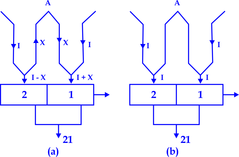
As segment 2 completes the process and contacts the brush, coil A experiences an increase in current flow. In order for the current in coil A to entirely reverse by the time the brush has reached segment 2, as seen in figure (d). Sparking is created on the surface of segment 1 with the brush during this full reversal of current. 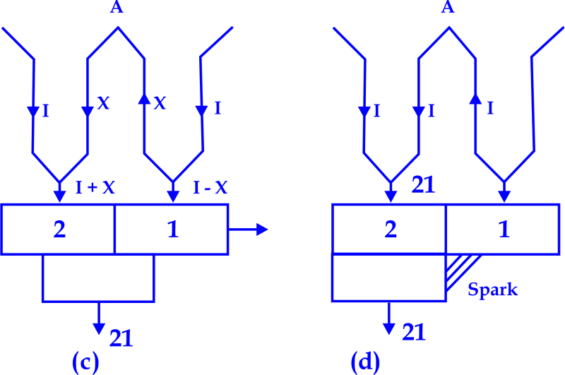
Thus, by increasing the brush-contact resistance (using carbon brushes with segments), sparking during current reversal may be prevented. The contact resistance is arranged such that the brush has a high resistance and the commutator segment has a reduced area of contact (segment 1 in the example in figure (c) above). |
 For Videos Join Our Youtube Channel: Join Now
Feedback
- Send your Feedback to [email protected]
Help Others, Please Share


