| |

Equivalent circuit of an Induction MotorStator's Equivalent Circuit:The stator model of an induction motor consists of a stator phase winding resistance R1, a stator phase winding leakage reactance X1. These two components appear to the right of the machine model. The no-load current I0 is simulated by a pure inductive reactor X0 taking the magnetizing component Iµ and a non-inductive resistor R0 carrying the core-loss current Iω. Thus, I0 = Iµ +Iω 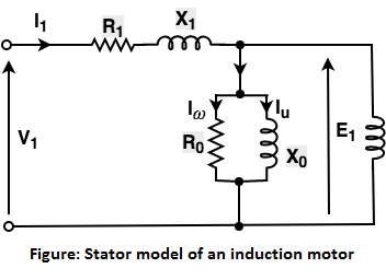 The magnetizing current in the case of the induction motor is higher than the transformer because the air gap of the induction motor causes higher reluctance. The magnetizing reactance X0 in an induction motor will have a much smaller value. In a transformer, I0 is about 2 to 5% of the rated current while in an induction motor it is approximately 25 to 40% of the rated current depending upon the size of the motor. Rotor's Equivalent Circuit:It an induction motor, when a 3φ supply is applied to the stator windings, a voltage is induced in the rotor windings of the machine. In general, the higher the relative motion of the rotor and the stator magnetic fields, the higher is the resulting rotor voltage. The maximum relative motion occurs when the rotor is stationary, this condition is called the Standstill condition. This is also known as the locked-rotor or blocked-rotor condition. If the induced rotor voltage is E20 then the induced voltage at any slip is given by, E2s = sE20 The rotor resistance R2 is constant. It is independent of slip. The reactance of the induction motor rotor depends upon the inductance of the rotor, voltage frequency, and rotor's current. If L2 = inductance of rotor, the rotor reactance is given by X2=2πf2 L2 But f2=sf1 ∴ X2=2π sf1 L2=s(2π f1 L2) Or X2=sX20 In the above equation, X20 is the standstill reactance of the rotor.  The rotor impedance is given by Z2s = R2 + jX2s Or Z2s = R2 + jsX20 The rotor current per phase is given as 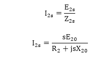 In the circuit drawn above, I2 is a slip-frequency current produced by a slip-frequency induced voltage sE20 acting in the rotor circuit having an impedance per phase of (R2 + jsX20). By dividing both the numerator and the denominator of the above equation by the slip s, we get 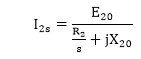  It is to be noted that the magnitude and phase angle of I2s remain the same by this operation. This equation describes the secondary circuit of a fictitious transformer, one with a constant voltage ratio and with the same frequency of both sides. This fictitious stationary rotor carries the same current as the actual rotating rotor, and, thus produces the same m.m.f wave. This concept of fictitious stationary rotor makes it possible to transfer the secondary impedance to the primary side.
Next Topic#
|
 For Videos Join Our Youtube Channel: Join Now
Feedback
- Send your Feedback to [email protected]
Help Others, Please Share


