| |

Speed Control of D.C. MotorsThe relationship given below gives the speed of a D.C. motor 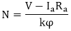
The above equation shows that the speed depends upon the supply voltage V, the armature circuit resistance Ra, and the field flux Ф, which is produced by the field current. In practice, the variation of these three factors is used for speed control. Thus, there are three general methods of speed control of D.C. Motors.
1. Armature resistance control (Rheostat Control):
Figure: (a) Speed control of a d.c. Shunt motor by armature resistance control. In this method, a variable series resistor Re is put in the armature circuit. The figure (a) above shows the process of connection for a shunt motor. In this case, the field is directly connected across the supply and therefore the flux Ф is not affected by variation of Re. Figure (b) shows the method of connection of external resistance Re in the armature circuit of a D.C. series motor. In this case, the current and hence the flux is affected by the variation of the armature circuit resistance. The voltage drop in Re reduces the voltage applied to the armature, and therefore the speed is reduced. This method has the following drawbacks:
This method is only used for small motors. 2. Variation of field flux Ф (Field flux control):Since the field current produces the flux, and if we control the field current then the speed can be controlled. In the shunt motor, speed can be controlled by connecting a variable resistor Rc in series with the shunt field winding. In the diagram below resistor, Rc is called the shunt field regulator. 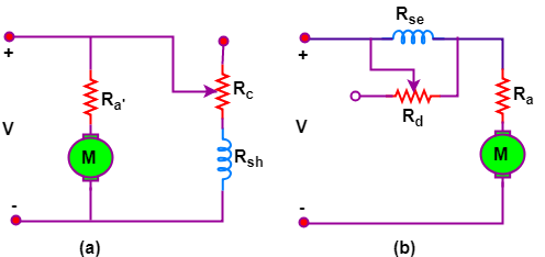
Figure: (a) Speed control of a D.C. shunt motor by variation of field flux.
Any of the one methods can vary the field current of the series motor:
Here the ampere-turns are varied by varying the number of field turns. This arrangement is used in electric traction. 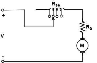
Figure: Tapped series field on D.C. motor The advantages of field control are as follows:
3. Armature Voltage control:We can control the speed of the D.C. motors by varying the applied voltage to the armature. Ward-Leonard system of speed control works on this principle of armature voltage control. In this system, M is the main dc motor whose speed is to be controlled, and G is a separately excited dc generator. The generator G is driven by a 3- phase driving motor which may be an induction motor or asynchronous motor. The combination of ac driving motor and the dc generator is called the motor-generator (M-G) set. 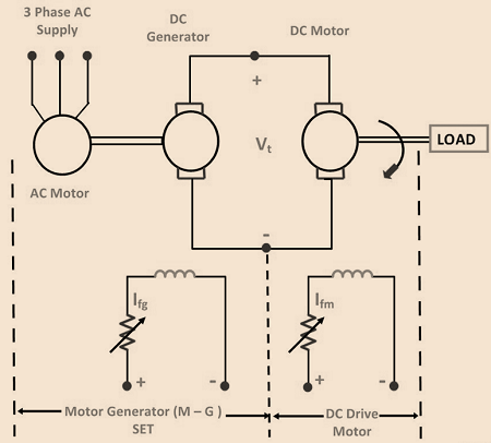
Figure: Ward-Leonard drive Advantages of Ward-Leonard Drives:
Drawbacks of classical Ward-Leonard system:
Next TopicStarting of D.C. Motors
|
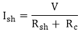 gives the shunt field current
  For Videos Join Our Youtube Channel: Join Now
Feedback
- Send your Feedback to [email protected]
Help Others, Please Share


