| |

Classification of TransmittersThe modulated wave is sent by the antenna located at the transmitter section's end. Transmitters are mainly classified into two ways: AM Transmitter and FM transmitter. We will discuss in detail about AM and FM transmitters in this article. After that we will discuss about Receivers. 1. AM TransmitterAn amplitude modulated wave is sent to the antenna by an AM transmitter, which receives the audio signal as its input and transmits it. The following figure displays the AM transmitter's block diagram. 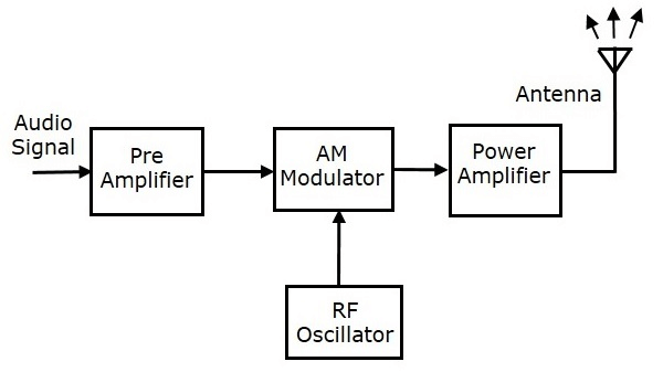
The following points will explain how an AM transmitter operates:
2. FM TransmitterFM transmitter is the whole unit, which takes the audio signal as an input and delivers FM waves to the antenna as an output to be transmitted. The block diagram of the FM transmitter is shown in the following figure. 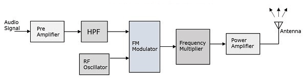
The following points will describe how an FM transmitter operates.
ReceiversThe modulated wave is picked up by the antenna at the start of the reception portion using receivers. Let's start by talking about what is expected of a receiver. Conditions for a ReceiverThe envelope detector is used by the AM receiver to demodulate the AM wave once it is received. Similar to this, an FM receiver picks up an FM signal and demodulates it using the frequency discrimination technique.
The tuner circuit and the mixing circuit must function extremely well to meet these criteria. A fascinating phenomenon is the RF mixing process. RF MixingTo properly handle any received signal, the RF mixing unit creates an Intermediate Frequency (IF), which is then converted to any received signal. The receiver's RF Mixer stage is crucial. To create the final mixed output, two signals of different frequencies are combined in such a way that the level of one signal influences the level of the other signal. The following figures show the input signals and the final mixer output. 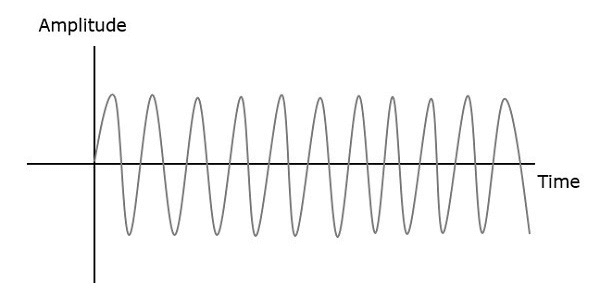
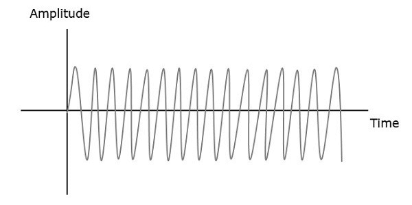
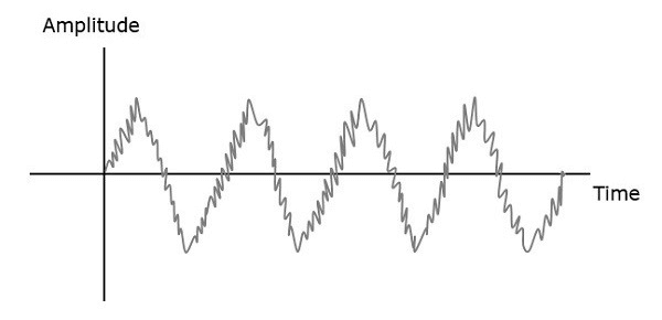
Let f1 and f2 represent the first and second signal frequencies. These two signals create an output signal with frequencies of f1+f2 and f1-f2 if they are supplied as inputs to an RF mixer. The pattern appears as seen in the following figure if this is noticed in the frequency domain. 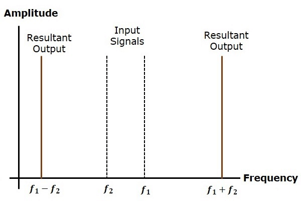
f1 is bigger than f2 in this situation. Thus, the output has the frequencies f1+f2 and f1-f2 as a consequence. The resulting output will have the frequencies f1+f2 and f1-f2 if f2 is larger than f1. Classification of ReceiverAM ReceiverThe amplitude modulated wave is sent into the AM super heterodyne receiver, which outputs the original audio stream. Selectivity refers to the capacity to accept some signals while rejecting others. Sensitivity is the ability to detect and demodulate an RF signal at the lowest possible power level. The first radio receivers were radio amateurs. They do, however, have shortcomings including inadequate sensitivity and selectivity. The invention of the super heterodyne receiver addressed these issues. The following figure displays the AM receiver's block diagram. 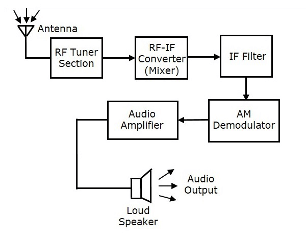
RF TunersA transformer transmits the amplitude modulated wave that the antenna has detected first to the tuner circuit. The tuner circuit is nothing more than an LC circuit, often known as a tank or resonant circuit. It chooses the frequency that the AM receiver wants. Additionally, it simultaneously adjusts the RF filter and the local oscillator. Mixer RFThe tuner output signal is routed to the RF-IF converter, which also serves as a mixer, where it is received. It features a built-in local oscillator that generates a steady frequency. Here, the mixing is carried out with the local oscillator frequency as one input and the received signal as the other. The mixer produces a blend of two frequencies,[(f1+f2),(f1-f2 )] known as the Intermediate Frequency, which is the final output (IF). Demodulation of any station signal with any carrier frequency is aided by the generation of IF. Therefore, for sufficient selectivity, all signals are converted to a set carrier frequency. IF FilterThe required frequency is sent via an intermediate frequency filter, which is a band pass filter. All additional undesirable frequency elements are taken out of it. This is the benefit of an IF filter, which only accepts IF frequencies. AM DemodulatorThe AM demodulator is now used to demodulate the received AM wave. The envelope detection method is used by this demodulator to capture the modulating signal. Audio BoosterThe detected audio signal is amplified at this step, known as the power amplifier. To be effective, the processed signal is enhanced. The loudspeaker receives this signal and outputs it as the original sound signal. FM ReceiverThe following figure displays the FM receiver's block diagram. 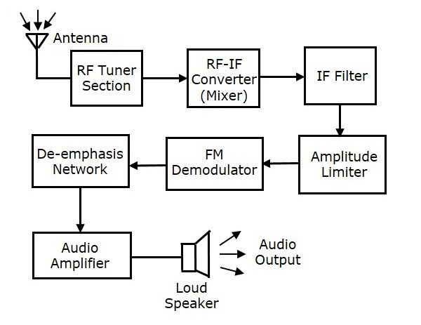
This FM receiver block diagram resembles the AM receiver block diagram. Amplitude limiter and De-emphasis network are the two blocks that come before and after the FM demodulator. The remaining blocks function like an AM receiver would. We know that the amplitude of the FM wave remains constant during FM modulation. However, the amplitude of the FM wave may change if additional noise is added to the channel. Therefore, by deleting the undesired peaks of the noise signal, we could maintain the amplitude of the FM wave as constant with the aid of an amplitude limiter. An FM transmitter has been seen with a pre-emphasis network (High pass filter), which is installed before the FM modulator. To increase the SNR of the high frequency audio signal, this is done. De-emphasis is the equivalent of pre-emphasis in reverse. This FM receiver then has a de-emphasis network (Low pass filter) added to it after the FM demodulator. This signal is delivered to the audio amplifier to increase the power. The loudspeaker then transmits the original audio signals to us.
Next Topic#
|
 For Videos Join Our Youtube Channel: Join Now
Feedback
- Send your Feedback to [email protected]
Help Others, Please Share


