| |

SSBSC (Single Sideband Suppress Carrier) TransmissionSSB means Single Sideband, i.e., only one sideband. If the carrier is suppressed or removed, the modulation is called SSBSC (Single Sideband Suppress Carrier). Otherwise, the modulation is termed as SSBC (Single Sideband with Carrier). SSBSC is used to transmit audio signals, such as speech signals and radio waves. SSBSC transmission does not require an additional sideband to recover the signal. A single sideband is enough for the transmission. It results in a low spectral range and low bandwidth, which increases the efficiency of the signal. SSB is commonly used in the long-distance transmission of speech signals. The bandwidth of the speech signal lies in the range 300 Hz and 3400 Hz. The maximum space between the two channels in SSB can be 4000 Hz. We have discussed that a baseband signal can be recovered from Double Sideband Suppress Carrier (DSBSC) by multiplying it with the same carrier second time. Now, what happens if there is only one sideband? Is the process of baseband recovery the same? Let's discuss. The spectral components of the baseband signal generate two sidebands in DSB of frequency ω + ωc and ω - ωc. Where, ωc is the carrier frequency ω is the baseband frequency If we filter out the lower sideband by multiplying it with the carrier signal, we get the frequency ω + 2ωc. If we filter out the upper sideband by multiplying it with the carrier signal, we get the frequency 2ωc- ω. In both cases, the baseband signal can be easily recovered. Hence, recovering the baseband signal from a single sideband is possible. It saves spectral space, which is an added advantage of SSB modulation. Two single modulation systems are required to occupy the spectral range in SSB, which was previously occupied by a single DSBSC transmission system. The Single Sideband transmission system consists of only a single sinusoidal. Here, the diode modulator to recover the baseband signal cannot be used. There is no such amplitude variation to which the modulator can respond. A pictorial representation of the generation of Single Sideband is shown below: 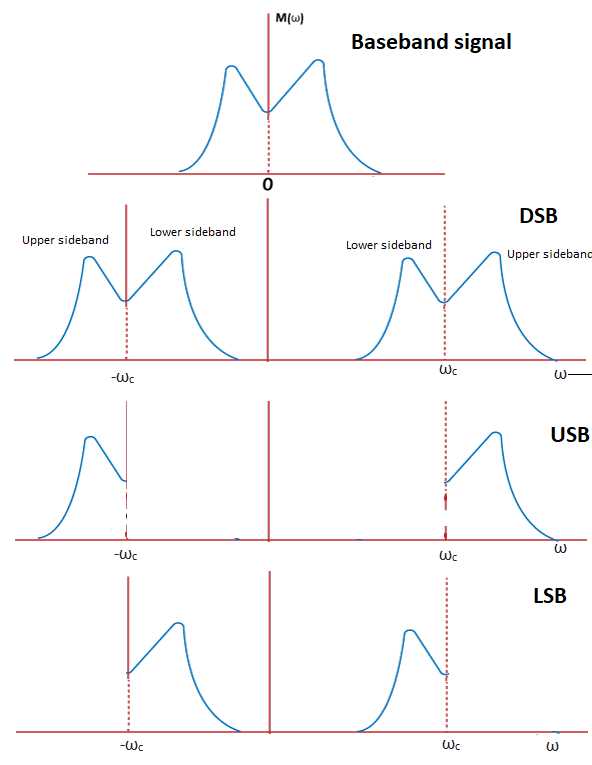
Where, DSB: Double Sideband USB: Upper Sideband LSB: Lower sideband USB shows the SSB modulation when the upper part of the sideband is filtered out. LSB shows the SSB modulation when the lower part of the sideband is filtered out. Mathematical Representation of SSBSCHilbert TransformIt is given by: Xh(t) = H {x(t)} Where, X(t) is the message signal 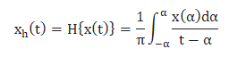
Where, Alpha is the variable taken for integration. Hilbert transform is almost like a convolution, which is x(t) * h(t) h(t) = 1/πt Any message signal m(t) with a phase shift of 90 degrees undergoes a Hilbert transform (mh(t)). The Fourier analysis of the Hilbert transform is given by: Fourier transform of mh(t) is -jsgn(ω)M(ω) M(ω) is the Fourier transform of the original signal m(t). The DSB representation of the signal when multiplied with the carrier is given by: MDSB = 0.5[M(ω + ωc) + M(ω - ωc)] The SSB representation of the lower sideband signal when multiplied with the carrier is given by: MSSB = 0.5 MDSB [sgn(ω + ωc) - sgn(ω - ωc)] MSSB = 0.5 x 0.5[M(ω + ωc) + M(ω - ωc)] [sgn(ω + ωc) - sgn(ω - ωc)] MSSB = 0.25 [M(ω + ωc) + M(ω - ωc)] [sgn(ω + ωc) - sgn(ω - ωc)] After multiplying, we get: MSSB = 0.25 [M(ω + ωc) sgn(ω + ωc) + M(ω + ωc) - sgn(ω - ωc) + M(ω - ωc) sgn(ω + ωc) + M(ω - ωc) - sgn(ω - ωc) Substituting the value- sgn(ω - ωc) = 1 and sgn(ω + ωc) = 1, we get; MSSB = 0.25 [M(ω + ωc) + M(ω - ωc)] + = 0.25 [M(ω + ωc) sgn(ω + ωc) - M(ω - ωc) sgn(ω - ωc) The inverse transform of the first term will produce the DSBSC signal 0.5m(t) cosωct. The inverse transform of the second term will produce the SSBSC lower sideband signal 0.5m(t) cosωct + 0.5mh(t) sinωct. Similarly, the inverse transform ofthe SSBSC upper sideband signal can be represented as 0.5m(t) cosωct - 0.5mh(t) sinωct. SSBSC ModulatorThere are two techniques to generate the single sidebands suppress carrier. The first technique uses the balanced modulator, filter, oscillator, etc., to generate SSBSC. The other method is the phase shift method. Here, we will discuss both methods in detail. The block diagram of the SSBSC modulator is shown below: 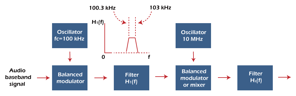
It consists of two balance modulators, two bandpass filters, and two oscillators. The baseband signals with the carrier are first applied to the balance modulator. The output of the modulator will be two sidebands, named as the upper sideband and the lower sideband. The next block after the balance modulator is the bandpass filter. In SSBSC, the filter needs to select only one sideband. Any one of the sidebands (upper or lower) is selected by the filter H1(f). In SSBSC, the filter needs to select only one sideband. The filter's cut-off frequency should be strong enough to separate the selected sideband from the other sideband. Its separation frequency is given by: Separation frequency = 2 (lowest frequency spectral component of the baseband signal) For example, If lowest frequency spectral component = 400 Hz Separation frequency = 2 x 400 = 800 Hz The range of the human speech is from 300 Hz to 3000 Hz. The sideband filter is selected to this range of frequency. Such restriction in SSB helps in conserving bandwidth. The response outside this Passband range falls off sharply. The maximum gap between the two channels is 4000 Hz. The carrier, along with the signal, does not appear at the output of the balanced modulator, i.e., it is suppressed. It can be further added in the case of SSBC (Single Sideband with Carrier) transmission. A balanced modulator cannot effectively balance both the baseband signal and the carrier signal. It also leads to variation with time. Here, two oscillators of carrier frequency 100k Hz and 10M Hz are used at the balance modulator. If only one oscillator of 10M Hz carrier frequency is used, the frequency change will be 0.006%, which is given by: Separation frequency = 2 x lowest frequency component = 2 x 300 Hz = 600 Hz The separation frequency of 600 Hz for 10M Hz oscillator result in the percentage of 600 Hz/10M Hz = 600/107 x 100 = 6 x 10⁴ / 107% = 0.006 % Filters with such percentage are very difficult to construct. Hence, it is essential to use two oscillators in the circuit. The first oscillator of carrier frequency 100k Hz is selected. The range of the USB (upper sideband) will be: (Carrier frequency + lower limit) to (carrier frequency + upper limit) = (100000 + 300) to (100000 + 3000) = (100300) to (103000) = 100.3k Hz to 103k Hz The percentage at the output of the first balance modulator will be: 600 Hz/100k Hz = 600/105 x 100 = 6 x 10⁴ / 105 % = 0.6% The output of the first modulator is applied to the filter. Suppose the filter selects the Upperband frequency of 100.3 kHz. Separation frequency = 2 x lowest frequency component = 2 x 100.3 = 200.6k Hz The output of the filter is now applied to the second balance modulator. The frequency change percentage now will be around 2%. = 200.6k Hz/ 10M Hz x 100 = 2% (Approx) In such cases, the frequency translation can be achieved in two stages. We are not required to use more than two stages. The succeeding stages after the first stage can use mixers instead of balance modulators if the baseband signal has the spectral components of low frequency. For example, Suppose the second stage was mixer instead of the balance modulator. The output of the balance modulator will be the lower and upper sidebands along with the oscillator carrier frequency. The range will become (10M Hz + 100.3k Hz) to (10M Hz + 103k Hz). The selected second filter needs to pass the upperband frequency from the range. The frequency change will be around 1%, which is also possible. Phase Shift methodAs the name implies, single sidebands can be generated using the phase shift of 90 degrees. It is derived from mathematical representation of the SSBSB modulation. The circuit comprises of two 90 degrees phase shift networks, two balance modulators, and an Adder or subtractor. The block diagram of the phase shift method is shown below: 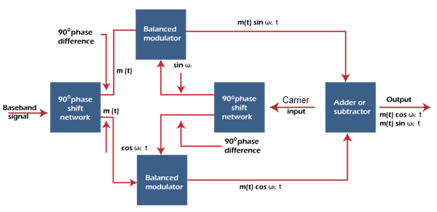
Suppose the baseband signal is sinusoidal. The output of the first phase shift network will be cosωct. A further phase shift of 90 degrees will produce the output sinωct at the output of the second phase shift network. The output of the two balance modulators will be: cosωct cosωmt = ½ [cos (ωc - ωm)t + cos (ωc + ωm)t] sinωct sinωmt = ½ [cos (ωc - ωm)t - cos (ωc + ωm)t] If these waveforms are added using the adder, the lower sidebands are produced. If subtracted using the subtractor, the upper sidebands are produced. The requirement of two phase shifters, proper balance modulator, adder, and subtractor makes the SSB transmission more complicated. SSBSC DemodulatorIn the first multiplication, the baseband signal was multiplied with the carrier signal to improve the signal's frequency. It is known as modulation. When it is again multiplied by the carrier signal, it is known as demodulation. The demodulation is used to recover the baseband signal from the modulated signal. It means the multiplication with the carrier signal at a second time helps recover the baseband signal. There are two methods for demodulation of SSB. The first method is the demodulation using coherent detection. The second method is the demodulation using an envelope detector used for SSB with the carrier. Here, we will discuss the first method for recovering baseband signal in SSBSC. Coherent detectionIn DSBSC, the baseband signal is recovered by multiplying it with the carrier signal at the receiving end. The carrier signal should be coherent to the carrier used at the transmitter. But, the synchronization process in SSB is different from DSB. The phase shift in the signal can either affect the amplitude of the signal or only the phase. An impact on the signal's amplitude may result in the total loss. A phase change does not produce much signal loss in the other case. A human ear is more sensitive to the amplitude offset error than the phase error. Hence, SSB is used to transmit audio signals because a phase error does not produce much change. If the carrier frequency is very high, it will be difficult for the oscillator to maintain the frequency. Hence, the carrier is necessary to transmit with the baseband signal. It can be separated using filters at the receiving end. It can be also transmitted at a reduced power level for synchronization. The equation of the SSBSC is given by: MSSB (t) = 0.5m(t) cosωct + 0.5mh(t) sinωct Where, mh(t) is the message signal with a 90 degree phase shift The modulated signal is multiplied by the carrier signal cosωct. MSSB (t) cosωct = [0.5m(t) cosωct + 0.5mh(t) sinωct] cosωct MSSB (t) cosωct = 0.5m(t) cosωc2t + 0.5mh(t) sinωct cosωct Y(t) = 0.25 m(t) [1 + cos2ωct] + 0.25mh(t) sin2ωct The signal is further passed through a low pass filter. It recovers the signal and suppresses the components around 2ωct. The first term (message signal) will be recovered. The block diagram of the SSB demodulator is shown below: 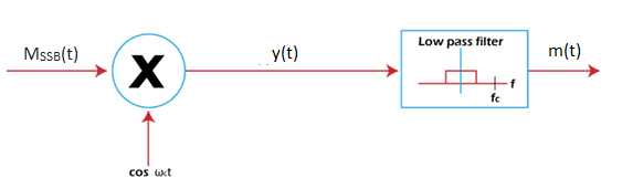
Where, M(t) is the message signal Y(t) is the output of the SSBSC demodulator MSSB (t) is the output of the SSBSC modulator cosωct is the coherent carrier signal Efficiency of SSBSCThe efficiency of SSBSC is 100%. It is the most efficient type of Amplitude Modulation. The efficiency of DSBC (Double Sideband with Carrier) is 33.33% and the efficiency of DSBSC (Double Sideband Suppress Carrier) is 50%. Why is the efficiency of SSB 100%?We know that the bandwidth of the SSB is reduced to half due to the absence of an extra sideband. It requires only one sideband for the efficient transmission of audio signals. In DSBSC, the efficiency was 50% due to the power divided between the two sidebands. Here, one sideband along with the carrier is suppressed. There is no such way for the power to get divided. Hence, the efficiency of SSBSC is 100%. Why video signals cannot be transmitted using SSBSC?The bandwidth requirement for the transmission of video signals is very large. SSBSC has low bandwidth. The complexity of the transmitters, receiver, and the low bandwidth of SSB does not make it suitable for video transmission. Hence, SSB is commonly preferred for the transmission of only audio signals. Noise analysis of SSBSCThe input of the SSBSC modulator consists of the baseband signal and the carrier signal, which is suppressed by the filter. The output of the SSBSC demodulator is only the baseband signal. The input of the demodulator consists of the modulated baseband signal with the synchronous locally generated carrier cos2πfct. Consider the below block diagram: 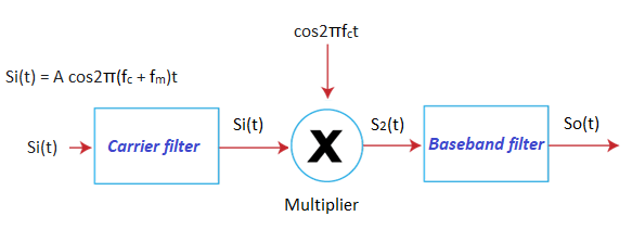
It has two filters and a multiplier. The first filter is the carrier filter that suppresses the carrier for efficient transmission. The second filter is the baseband filter that recovers the baseband signal. The multiplier is present between the two filters. It multiplies the modulated signal with the coherent carrier signal to help in the recovery of the baseband signal. The frequency of the filter extends from fc to fm. The output of the carrier filter is: Si(t) = A cos2π(fc + fm)t The output of the multiplier is: S2(t) = Si(t) cosωct = A/2 cos2π(2fc + fm) t + A/2 cos2πfmt The output signal is: So(t) = A/2 cos2πfmt The modulated signal is amplified by the factor 1/2 The input signal power is: Si = A2/2 The output signal power is: So = ½ (A/2)2 So = A2/8 = Si/4 The ratio of output to input signal power is given by: So/Si = 1/4 The input noise is white with the spectral density of n/2. When a noise component f is multiplied with carrier signal, it gets replaced by two components of frequency fc + f and fc - f. The total noise output of SSBSC is given by: No = 2fM n/8 No = nfM/4 Advantages of SSBSCThe advantages of SSBSC are as follows:
Disadvantages of SSBSCThe disadvantages of SSBSC are as follows:
ApplicationsIt is used in various applications that require low power consumption, low bandwidth, and long distance transmission. The applications of SSBSC are listed as follows:
Next TopicSSBC
|
 For Videos Join Our Youtube Channel: Join Now
Feedback
- Send your Feedback to [email protected]
Help Others, Please Share


