| |

Pulse Amplitude Modulation (PAM)PAM is a type of pulse modulation where the amplitude of the pulse is varied with the sample value of the message signal. Pulse modulation techniques are widely used in digital transmission, where non-baseband applications are replaced by PPM (Pulse Position Modulation). PAM modulation technique is used in various applications, such as Ethernet, television, and LED lighting. Here, we will discuss the process used to transmit the number of pulses from different sources using TDM. It represents how the analog data is transmitted by its discrete samples. We have assumed that the samples are in the form of a pulse of finite width. The method used to send the number of signals from different sources one after the other in a specific time band is known as TDM (Time Division Multiplexing). It is also used in digital modulation to transmit the codes in binary. When the amplitude of the pulse carries the message information of the baseband signal, it is known as PAM (Pulse Amplitude Modulation). If it is carried by width, it is known as PWM (Pulse Width Modulation), and if by position, it is known as PPM (Pulse Position Modulation). The combination of PWM and PPM is known as PTM (Pulse Time Modulation). Among all the available modulation schemes, PAM is suitable for TDM and digital representation. Let's consider a PAM technique that uses the sampling principle and time multiplexing for the signal representation and transmission. The block diagram is shown below: 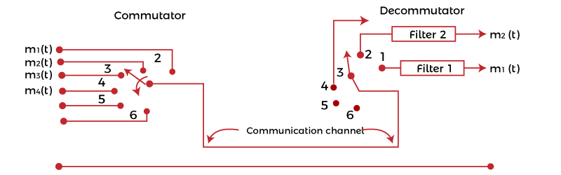
At both ends, rotary switches in synchronization are connected, representing the transmitting and the receiving end. On the left side, various bandlimited signals are connected to the contact point of a rotary switch. Bandlimited refers to the signals sent at the specific threshold or the cut-off frequency. If the frequency rises above the cut-off frequency, the amplitude of such signals goes to zero. For example, voice signals are bandlimited to 3.3k Hz. When the rotary arm of the switch swings, it samples every signal sequentially. The other signal at the receiving end makes contacts simultaneously with the same numbered contacts. With every revolution f the switch, each signal was sampled and presented at the corresponding contact number at the receiving end. The sampled signal at the end passes through the LPF (Low Pass Filter) and we get the original recovered signal. For a sampled signal numbered 1, we get the message signal m1(t). Similarly, for the signal numbered 2, we get the message signal m2(t). The revolutions are atleast twice the maximum frequency of the modulated signal. If FM is the highest frequency of the modulated signal, there were atleast 2FM revolutions per second. When the signal to be multiplexed varies slowly with time, mechanical switches can be used for signal recovery. In case of high speed applications, the operating power of the mechanical switches goes out of range. If the signal to be multiplexed varies with greater speed with time, an electronic switching system is used. In any of the above cases, the left side represents the transmitting end, and the right side represents the receiving end. The left side is known as the commutator, and the right side is known as decommutator. The signals are sampled at regular intervals of time duration TS. The Sampling of the second message signal is the same as that of the first, but the sampling time is different. Thus, the time of each sampling signal is different from the succeeding one. It is done to allow easy multiplexing and prevent the signals from interference. The transmissions of two trains of pulses that are modulated in amplitude are known as Pulse Amplitude Modulation. Multiplexing of various signals is possible if the signals are sampled at different times. It also allows their easy reconstruction at the receiving end. If the signals are separated by different frequencies, the system is known as FDM (Frequency Division Multiplexing). If we want to transmit the signal from one antenna to the other direction, we need to modulate the signal (AM or FM) at a high carrier frequency. Channel bandwidth of PAMLet's consider the N number of baseband signals containing message information. Each signal is bandlimited to FM and represented by m1(t), m2(t), … mn(t). The communication channel does not require a bandwidth larger than NFM. The sampling of the baseband signal m1(t) is not greater than the time interval Ts = 1/2FM. It means that the successive signals are also sampled at the same time interval gap (1/2FMN). It is the gap between the two successive signals (for example, m1(t) and m2(t)). If the channel bandwidth is high, demultiplexing would be easier and can be achieved directly. But, if the channel bandwidth is restricted, the basebands signals may combine resulting in crosstalk, which may affect the quality of the signal. A low pass filter is used to recover the message signal at the output in a similar way like other modulation processes. Suppose the first baseband signal is transmitted at t = 0. The response will be represented by: S1 = I1ωc sin ωct/πωct At t = 0, the response shows the peak proportional to the message signal m1(t). The second baseband signal needs to be transmitted at t= 1/2FC. The response IS GIVEN BY: S2 = I2ωc sin ωc (t - 1/2FC)/πωc(t - 1/2FC) The response of both the baseband signals is shown below: 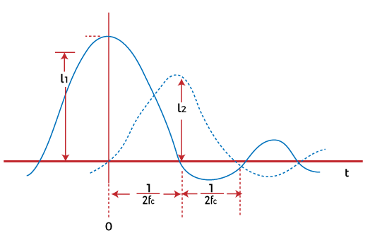
The dashed line represents the response of the second baseband signal. The Sampling at time intervals prevents the crosstalk with the recovery of the original baseband signals m1(t) and m2(t). Natural SamplingWe have discussed the instantaneous Sampling of baseband signals, which is the process of sending multiple signals using electronic switches. It was based on the revolution of rotary switches present at both the transmitting and receiving ends. But, sampling using such switches is not feasible. The energy of the instantaneous samples is sometimes infinite. It gives rise to small peak values that may introduce back noise in the signals. Hence, Natural Sampling is considered an efficient multiplexing method in Pulse Amplitude Modulation. Here, the sampling waveform S(t) consists of a train of pulses of duration τ. The sampled signal S(t)m(t) consists of a train of pulses following the waveform of the message signal m(t). The top of the signal S(t) also follows the pattern of the message waveform. The waveforms of the message signal m(t), sampling signal S(t), and the sampled signal S(t)m(t) are shown below: 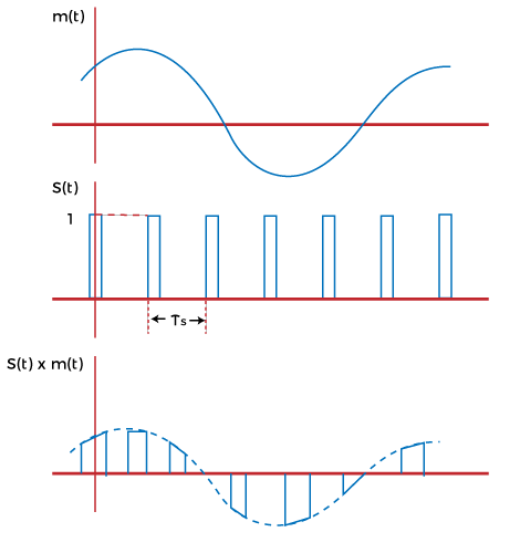
Like instantaneous sampling technique, it passes the sampled signals through the low pass filter with the cut-off frequency FM to recover the original message signal. The sampling waveform is represented by: S(t) = τ/TS + 2 τ/TS (C1cos2π t/ TS + C2cos4π t/ TS + … ) Where, Cn = sin(nπτ/TS)/(nπτ/TS) The sampled signal S(t)m(t) is given by: S(t)m(t) = m(t) τ /TS + 2 τ /TS (m(t)C1cos2π t/ TS + m(t)C2cos4π t / TS + … ) Flat top SamplingIn the natural sampling process, the sampled waveform follows the shape of the message waveform. It is not used frequently. Instead, the flat top sampling process is used. Though, the reconstruction of the original message signal is not easy. But, the design of flat top sampling electronic circuitry is simple as compared to the natural sampling process. 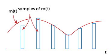
The baseband signal = m(t) The Fourier transform of the baseband signal = M(jω) The spectral density of flat-top sampling process is given by: Spectral density = τ sin(ωτ/2) / (ωτ/2) M(jω) The message signal has a flat spectral density over the range 0 to FM. The original signal can be recovered if the spectral density of the sampled signal and the original message signal are the same. The signal recovery can be performed using a low pass filter, as discussed above. The transfer function of the network is given by: H(jω) = τ /dT sin(ωτ/2) / (ωτ/2) The transform using the product of H(jω) and M(jω) is given by: Transform = τ /TS sin(ωτ/2) / (ωτ/2) M(jω) Signal recovery through holdingWe have discussed that the time interval between the different message signals is T/TS = 1/N. N is the total number of signals that need to be multiplexed. As N becomes larges, the time interval T/TS becomes smaller. Signal recovery through holing is an alternative signal recovery process that does not use amplifiers to raise the output level. The amplifiers are avoided because they may introduce noise in the circuit. Here, the flat top sampled is taken, as discussed above. The output waveform is the same as the flat-top signal except for the holding part. The sampled pulses are extended and held until the next signal occurs. It means that there is no gap between the two adjacent pulses. The extension is represented with the dashed line in the sampled waveform, as shown below: 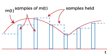
The circuit through which the holding operation is performed is shown below: 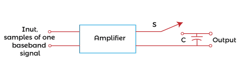
The switch is connected with the amplifier and a capacitor. The switch opens before the occurrence of the edge with no voltage. The switch closes after the occurrence of the edge of a sample pulse, allowing the capacitor to charge. It holds the voltage until the next operation is repeated. The amplifier selected for the process is a low impedance amplifier. The baseband signal = m(t) The Fourier transform of the baseband signal = M(jω) We consider that the received samples are the flap top samples to encompass the interval between the instantaneous samples. The spectral density of sampled and the held signal is given by: Spectral density = sin(ωTs/2) / (ωTs/2) M(jω) It is the same as the density of the flap-top sampling process, except the T is replaced by the sampling time. The magnitude of the sampled and held spectrum is shown below: 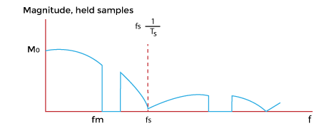
The unequal waveform is due to some distortion using the flat-top sampling process in the range 0 to FM. But, the distortion can be corrected by using an equalizer. It helps in removing distortion from the sampled signal. In audio instruments, it helps in removing unwanted sounds. The magnitude of the instantaneous sampled signal is shown below: 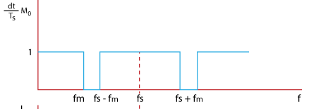
Advantages of PAMThe advantages of Pulse Amplitude Modulation are as follows:
Disadvantages of PAMThe disadvantages of Pulse Amplitude Modulation are as follows:
Next TopicPulse Time Modulation (PTM)
|
 For Videos Join Our Youtube Channel: Join Now
Feedback
- Send your Feedback to [email protected]
Help Others, Please Share


