| |

Radio TransmitterThe transmission of amplitude modulated signal is based on the radio transmitter and receiver. It is also useful in other types of modulation, including digital modulation. The radio transmitter is an electronic device that produces radio waves and radiates these waves with the help of an antenna. The antenna transmits the radio waves from one end to the other, which is captured by the other antenna present at the receiver end. Thus, data transmission is a communication between the transmitter and the receiver. Let's first discuss the transmitter and its components. TransmitterThe transmitter is the device that sends information. It communicates using wireless or wired media. Examples include cell phones, Bluetooth, walkie-talkies, computer networks, radio, and television broadcasting. A transmitter can be a component in an electronic device or a separate component in the circuit. The purpose of transmitters is to transmit the information over a certain distance. Components of a transmitterWe know that a communication channel consists of three main components, the transmitter, the communication channel, and the receiver. The transmitter is not a single component. It also involves a few components before transmitting the signal to the communication channel. The components of a transmitter are a transducer, processor, and transmitter. The circuit of a transmitter is shown below: 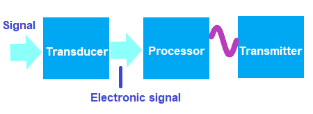
Transducer The transducer converts the signal's energy to electrical energy to make it suitable for transmission. For example, Sound energy Sound as the input is converted to the electrical form (electronic signal), which travels through different media, such as optical fiber, cables, etc. Processor The function of the processor is to analyze, interpret, and modify the signal for efficient transmission. Transmitter The transmitter directly sends the signal to the channel, which is further perceived by the receiver. The information travels through the channel and reaches the receiver. The components of the receiver are the same as a transmitter but connected oppositely. The transmitter takes the input from the user, converts it into a suitable form for transmission, and sends it to the receiver through the communication channel. The receiver captures the information, converts it back into the original form, and sends it to the receiver's output. The components of the receiver are the receiver and the transducer. The circuit of the receiver is shown below: 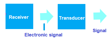
The receiver captures the information and sends it to the transducer. It converts the signal from the electrical form to its original form to make it suitable for perception at the output. Here, we will discuss the radio transmitters, components of radio transmitters, history, and the regulation of radio transmitter.. Radio transmitterA simple block diagram of a radio transmitter is shown below: 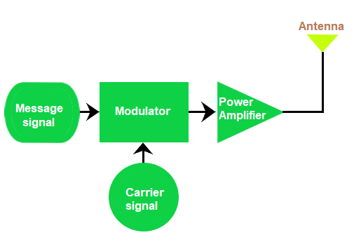
It consists of a message signal, modulator, carrier signal, power amplifier, and an antenna. As the name implies, the transmitter sends the information from one end to the other. The baseband signal, also known as the message signal, is translated to a radio frequency using modulation. The baseband signal is multiplied by the carrier signal by the modulator. It helps in improving the frequency of the signal. The selected carrier signal has the same amplitude as the original signal. A power amplifier further amplifies the signal and radiates through the antenna. It combines the input and high-frequency carrier signals, also known as modulation. We can add the information to the carrier in different ways. It depends on the types of modulation and the types of the transmitter. In the case of AM (Amplitude Modulation), the information is added by varying its amplitude. The message signal and the carrier signal are present at a constant amplitude. Similarly, in the case of FM (Frequency Modulation), the information is added by varying its frequency. The radio signal from the transmitter is transmitted with the help of an antenna. It radiates the energy in space. The antenna is attached openly or in a closed case, such as mobile phones and walkie-talkies. In large power applications, the antenna outside the transmitter device is located on the top of a building or as a separate power (transmission lines). An Am broadcast antenna occupies the bandwidth of 10k Hz. If the carrier signal is of the frequency 500k Hz, the frequency range of the transmitter will be: Fc - Fm to Fc + Fm Bandwidth = 2Fm Fm = 10/2 = 5k Hz = (500 - 5) to (500 + 5)k Hz The frequency range is 495k Hz to 505k Hz. The oscillator used for generating carrier signal is made of LC crystal, which is not much stable. Hence, the output of the modulator passes through the amplifier that helps in increasing the power level of the signal. It also behaves as an isolator to prevent the variation of load affecting the oscillator's frequency. The components in the radio transmitter are not connected directly. The Impedance matching networks connect one stage with the other, which will be discussed later in the topic. The components of the radio transmitter are listed as follows:
Let's discuss each component in detail. Power AmplifierThe function of the power amplifier is to provide a power boost to the signal. A simple modulator radiates only a few milliwatts of power, while an AM broadcast can deliver several kilowatts of power. Here, a class C power amplifier is preferred for the transmission. These amplifiers' half of the input signals have high distortion but produce 90% power efficiency. The distortion is reduced by using tuned loads with the amplifier. The block diagram of the power amplifier is shown below: 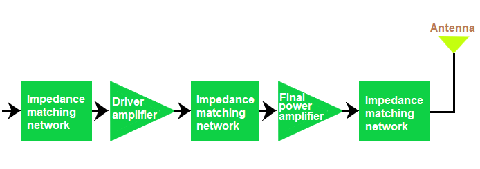
The components of a power amplifier are three impedance matching networks, one driver amplifier, and one final power amplifier. The first driver amplifier provides an intermediate power boost, while the final amplifier provides the required boost. A class A amplifier is used in the buffer stage in case of high bandwidth requirements. But, its efficiency is low. Such amplifiers conduct even when the input signal is absent, which results in power loss. Impedance matching networksAs discussed, impedance matching networks provides efficient power coupling between two stages. It also works as a filtering device to remove any unwanted signal from the information. The output impedance and the input impedance of the first and the next stage are made equal for maximum power transfer between the two stages. The LC networks, loads, and transformers are used in these networks. Transformer based impedance matching network uses turn ratio to match the load. It also uses special type of core material and copper windings to prevent the leakage of magnetic energy especially at high frequencies. The impedance matching process involves the matching of the resistive load and reactive load of the output impedance of the first stage and the input impedance of the second stage. Mostly, the resistive load is an inductor (L) and the reactive load is the capacitor (C). The same process is carried out for complex networks. It is also known as the LC network. AntennaThe antenna is connected at the end of the radio transmitter. It radiates the energy through the communication channel to the receiver. When current enters the antenna, the electrical conductor inside it generates the magnetic field. It further induces an electric field. Both the electric and magnetic fields form the EM waves, which travel with the speed of light in a direction directed by the antenna. The shape and size of the antenna depend on the wavelength of operation. The simplest type of antenna is the half-wave dipole antenna. It has a single wire with a length equal to half of its wavelength. The entire signal reaching the antenna in not radiated. A part of the signal is reflected back. The remaining part of the signal provides the ohmic losses and the radiation power. The radiation power is used for radiating purposes. The radiation resistance of the antenna provides the same ohmic losses as by the radiation power. The efficiency of the antenna is given by: n = Prad/ Pin Where, N is the efficiency Prad is the radiation power Pin is the input power For further detailed information on antenna, click on the link antenna History
Regulation of radio transmitterThe information is transmitted at various frequencies. No two transmitters can transmit at the same frequency. It helps in the safe transmission and radio operation. It will cause interference, and the two channels may intersect. It also results in the loss of information. Thus, the transmitters are licensed and restricted to certain frequencies and power levels in most countries. The allocation of frequency bands to various classes is under ITU (International Telecommunication Unit). Apart from the licensed transmitters, there are also some short power transmitters. These are unlicensed and involve products like Bluetooth, cell phones, Wi-Fi, microphones, and baby monitors. Such consumer devices can operate without a license but are pre-approved before operation. It comes under the regulations of the FCC (Federal Communication System). |
 For Videos Join Our Youtube Channel: Join Now
Feedback
- Send your Feedback to [email protected]
Help Others, Please Share


