| |

MultiplexerA multiplexer is a combinational circuit that has 2n input lines and a single output line. Simply, the multiplexer is a multi-input and single-output combinational circuit. The binary information is received from the input lines and directed to the output line. On the basis of the values of the selection lines, one of these data inputs will be connected to the output. Unlike encoder and decoder, there are n selection lines and 2n input lines. So, there is a total of 2N possible combinations of inputs. A multiplexer is also treated as Mux. There are various types of the multiplexer which are as follows: 2×1 Multiplexer:In 2×1 multiplexer, there are only two inputs, i.e., A0 and A1, 1 selection line, i.e., S0 and single outputs, i.e., Y. On the basis of the combination of inputs which are present at the selection line S0, one of these 2 inputs will be connected to the output. The block diagram and the truth table of the 2×1 multiplexer are given below. Block Diagram: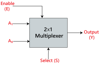
Truth Table: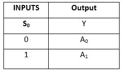
The logical expression of the term Y is as follows: Y=S0'.A0+S0.A1 Logical circuit of the above expression is given below: 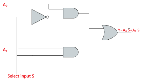
4×1 Multiplexer:In the 4×1 multiplexer, there is a total of four inputs, i.e., A0, A1, A2, and A3, 2 selection lines, i.e., S0 and S1 and single output, i.e., Y. On the basis of the combination of inputs that are present at the selection lines S0 and S1, one of these 4 inputs are connected to the output. The block diagram and the truth table of the 4×1 multiplexer are given below. Block Diagram: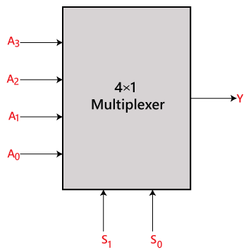
Truth Table: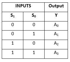
The logical expression of the term Y is as follows: Y=S1' S0' A0+S1' S0 A1+S1 S0' A2+S1 S0 A3 Logical circuit of the above expression is given below: 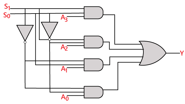
8 to 1 MultiplexerIn the 8 to 1 multiplexer, there are total eight inputs, i.e., A0, A1, A2, A3, A4, A5, A6, and A7, 3 selection lines, i.e., S0, S1and S2 and single output, i.e., Y. On the basis of the combination of inputs that are present at the selection lines S0, S1, and S2, one of these 8 inputs are connected to the output. The block diagram and the truth table of the 8×1 multiplexer are given below. Block Diagram:
Truth Table: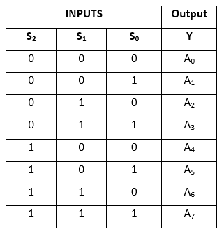
The logical expression of the term Y is as follows: Y=S0'.S1'.S2'.A0+S0.S1'.S2'.A1+S0'.S1.S2'.A2+S0.S1.S2'.A3+S0'.S1'.S2 A4+S0.S1'.S2 A5+S0'.S1.S2 .A6+S0.S1.S3.A7 Logical circuit of the above expression is given below: 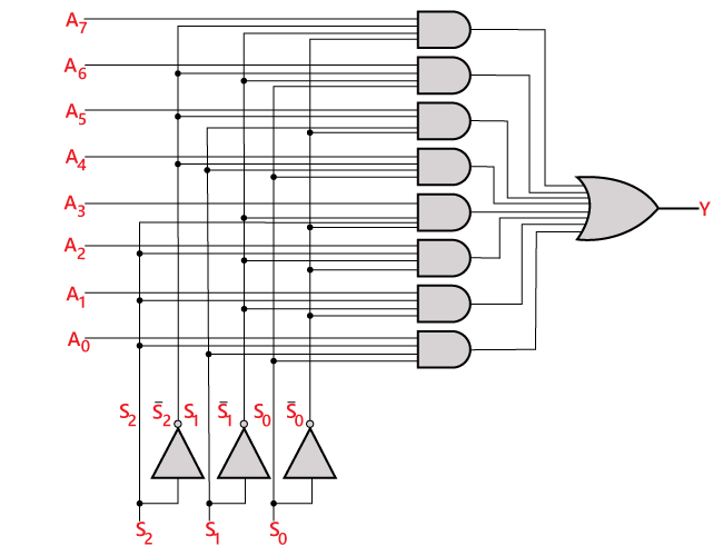
8 ×1 multiplexer using 4×1 and 2×1 multiplexerWe can implement the 8×1 multiplexer using a lower order multiplexer. To implement the 8×1 multiplexer, we need two 4×1 multiplexers and one 2×1 multiplexer. The 4×1 multiplexer has 2 selection lines, 4 inputs, and 1 output. The 2×1 multiplexer has only 1 selection line. For getting 8 data inputs, we need two 4×1 multiplexers. The 4×1 multiplexer produces one output. So, in order to get the final output, we need a 2×1 multiplexer. The block diagram of 8×1 multiplexer using 4×1 and 2×1 multiplexer is given below. 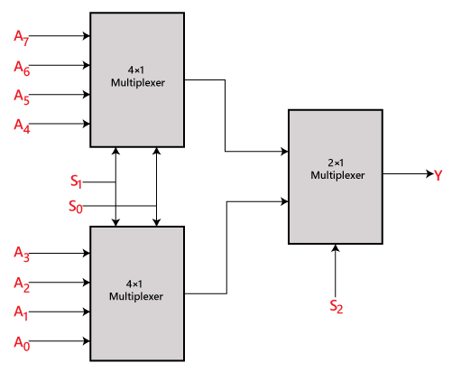
16 to 1 MultiplexerIn the 16 to 1 multiplexer, there are total of 16 inputs, i.e., A0, A1, …, A16, 4 selection lines, i.e., S0, S1, S2, and S3 and single output, i.e., Y. On the basis of the combination of inputs that are present at the selection lines S0, S1, and S2, one of these 16 inputs will be connected to the output. The block diagram and the truth table of the 16×1 Block Diagram: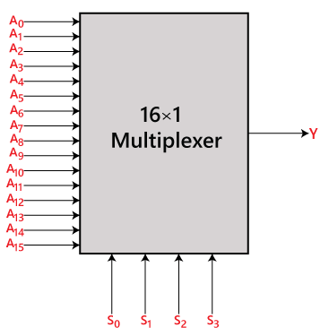
Truth Table: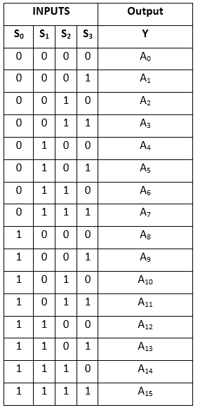
The logical expression of the term Y is as follows:
Y=A0.S0'.S1'.S2'.S3'+A1.S0'.S1'.S2
'.S3+A2.S0'.S1'.S2.S3'+A3.S0'.S1
'.S2.S3+A4.S0'.S1.S2'.S3'+A5.S0
'.S1.S2'.S3+A6.S1.S2.S3'+A7.S0
'.S1.S2.S3+A8.S0.S1'.S2'.S3'+A9
.S0.S1'.S2'.S3+Y10.S0.S1'.S2.S3
'+A11.S0.S1'.S2.S3+A12 S0.S1.S2
'.S3'+A13.S0.S1.S2'.S3+A14.S0.S1
.S2.S3'+A15.S0.S1.S2'.S3
Logical circuit of the above expression is given below: 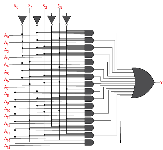
16×1 multiplexer using 8×1 and 2×1 multiplexerWe can implement the 16×1 multiplexer using a lower order multiplexer. To implement the 8×1 multiplexer, we need two 8×1 multiplexers and one 2×1 multiplexer. The 8×1 multiplexer has 3 selection lines, 4 inputs, and 1 output. The 2×1 multiplexer has only 1 selection line. For getting 16 data inputs, we need two 8 ×1 multiplexers. The 8×1 multiplexer produces one output. So, in order to get the final output, we need a 2×1 multiplexer. The block diagram of 16×1 multiplexer using 8×1 and 2×1 multiplexer is given below. 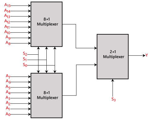
Next TopicDe-multiplexer
|
 For Videos Join Our Youtube Channel: Join Now
Feedback
- Send your Feedback to [email protected]
Help Others, Please Share


