| |

Ripple CounterRipple counter is a special type of Asynchronous counter in which the clock pulse ripples through the circuit. The n-MOD ripple counter forms by combining n number of flip-flops. The n-MOD ripple counter can count 2n states, and then the counter resets to its initial value. Features of the Ripple Counter:
Based on their circuitry design, the counters are classified into the following types: Up Counter The up-counter counts the states in ascending order. Down Counter The down counter counts the states in descending order. Up-Down Counter The up and down counter is a special type of bi-directional counter which counts the states either in the forward direction or reverse direction. It also refers to a reversible counter. Binary Ripple CounterA Binary counter is a 2-Mod counter which counts up to 2-bit state values, i.e., 22 = 4 values. The flip flops having similar conditions for toggling like T and JK are used to construct the Ripple counter. Below is a circuit diagram of a binary ripple counter. In the circuit design of the binary ripple counter, two JK flip flops are used. The high voltage signal is passed to the inputs of both flip flops. This high voltage input maintains the flip flops at a state 1. In JK flip flops, the negative triggered clock pulse use. 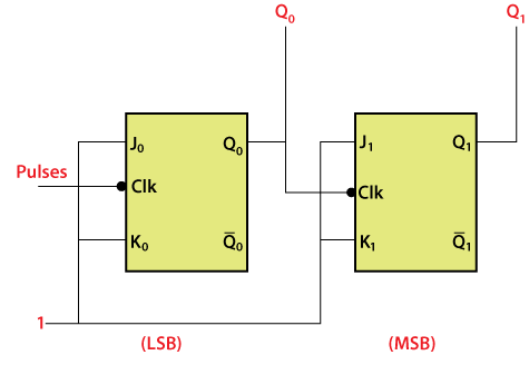
The outputs Q0 and Q1 are the LSB and MSB bits, respectively. The truth table of JK flip flop helps us to understand the functioning of the counter. 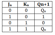
When the high voltage to the inputs of the flip flops, the fourth condition is of the JK flip flop occurs. The flip flops will be at the state 1 when we apply high voltage to the input of the flip-flop. So, the states of the flip flops passes are toggled at the negative going end of the clock pulse. In simple words, the flip flop toggle when the clock pulse transition takes place from 1 to 0. 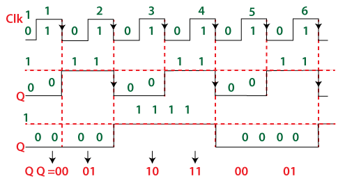
The state of the output Q0 change when the negative clock edge passes to the flip flop. Initially, all the flip flops are set to 0. These flip flop changes their states when the passed clock goes from 1 to 0. The JK flip flop toggles when the inputs of the flip flops are one, and then the flip flop changes its state from 0 to 1. For all the clock pulse, the process remains the same. 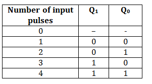
The output of the first flip flop passes to the second flip flop as a clock pulse. From the above timing diagram, it is clear that the state of the second flip flop is changed when the output Q0 goes transition from 1 to 0. The outputs Q0 and Q1 treat as LSB and MSB. The counter counts the values 00, 01, 10, 11. After counting these values, the counter resets itself and starts counting again from 00, 01, 10, and 1. The count values until the clock pulses are passed to J0K0 flip flop.
Next TopicRing counter
|
 For Videos Join Our Youtube Channel: Join Now
Feedback
- Send your Feedback to [email protected]
Help Others, Please Share


