| |

Structured Analysis vs Structured Design (SA/SD)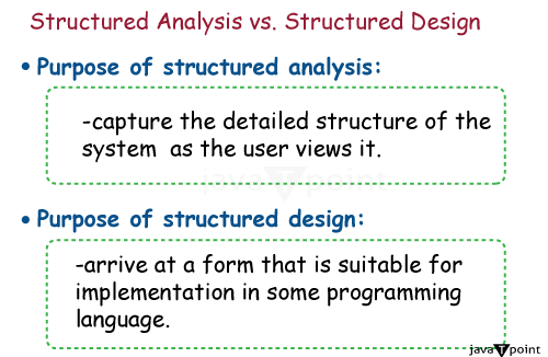
Structured AnalysisStructured Analysis is a method in software engineering that focuses on understanding, writing down, and evaluating a system's requirements in an organized and systematic way. It portrays processes, information streams, and information elements inside an association utilizing graphical instruments, for example, Information Stream Charts (DFDs) and Substance Relationship Outlines (ERDs). Structured analysis aims to show how the system works and how data moves through it in a clear and organized way. Key components1. Data flow diagrams (DFD): Definition: Data flow diagrams (DFDs) are graphical tools that depict how data flows across a system. They demonstrate how data moves through processes, repositories, and organizations. Key Components: - Processes: The actions or functions that convert input data into output data. - Data flows represent transfer between processes, data stores, and external entities. - Information Stores are archives where information is put away. - Outside Substances: These elements that interface with the framework but are part of it. 2. Dictionary of Data: Definition: A Data Dictionary is a centralized repository for the data items, structures, and relationship definitions and descriptions. Key Components: Data elements are basic units of information. Data structures are collections of data items. Data Relationships: Information on how data elements or structures are related. 3. Process Specifications: Definition: Process specifications are thorough descriptions of the processes listed in the DFDs. They are concerned with the activities carried out within each process and the data transformations. Key Components: Input: A description of the input data needed by the operation. Processing logic: A step-by-step explanation of the activities carried out by the process. Output: A description of the data generated by the procedure. 4. Entity Relationship Diagrams (ERDs): Definition: ERDs speak to information substances and their connections inside a framework.They give a visual representation of the data structure. Key Components: Entities: Represent items or concepts like consumers, products, etc. Ascribes are qualities or properties of elements. Connections will be associations or relationships between at least two elements. 5. Diagrams of Control Flow (CFD): Definition: CFDs show the control flow or sequence of actions within a module or process. They show the logical order in which actions are conducted. Key Components: Processes represent activities or tasks. Control Flows: Defines the order in which operations are performed. 6. Pseudocode: Definition: High-level description of module logic and functionality. It is an algebraic description not based on a specific programming syntax language. Main parts: Sequential statements describe steps that must be performed in a specific order. Conditional statements mean decisions or branches of logic. Loop statements describe repeated operations. Advantages of Structured Analysis:
Limitations of Structured Analysis:1. Rigidity: Structured analysis can be stiff and difficult to adapt to changes as the project progresses. Any changes to the system may necessitate considerable revisions to the analysis artefacts. 2. Complexity in large systems: Diagrams and documentation can become complicated to manage in larger systems. This complexity may limit the efficiency of Structured Analysis in such circumstances. 3. Not Agile Friendly: The structured analysis methodology is unsuitable for agile development methodologies, which involve frequent iterations, adaptability to changing requirements, and a focus on producing working software in short cycles. 4. Focus on the process, not the user interface: Structured analysis focuses on processes and data flow, with less attention on the system's user interface. In current software development, user experience is an important consideration. Application of Structured Analysis:i) Modeling the business processes: Structured Analysis can be used to model and analyse business processes. Organizations can get insights into how data moves through various processes and improve efficiency by employing tools such as Data Flow Diagrams (DFDs). ii) Designing Information Systems SA is used to build information systems, particularly in cases where understanding data flow and the relationships between distinct entities is critical. This is relevant in fields such as database design and information system architecture. iii) Maintaining legacy systems: Organizations still use Structured Analysis to maintain and improve legacy systems. The framework of the analysis aids in understanding and modifying current systems. iv) Education and Training. School programs focused on software engineering, information systems, and business analysis frequently cover structured analysis ideas. It establishes a basis for students to comprehend system requirements and design ideas. v) Documentation: SA is useful for comprehensively documenting a system. This documentation is used as a reference by developers, maintainers, and stakeholders to understand the structure and operation of the system. Workflowi) Understanding the system Begin by understanding the problem domain and the system's needs. Engage with stakeholders to learn more about the system's intended purpose. ii) Context Diagrams: Make a setting chart that outlines the framework and its outer substances. The system's primary inputs and outputs and interactions with the environment outside can be identified with the help of the context diagram. iii) Level 0 Information Stream Outline (DFD):Make a level 0 DFD that addresses the framework's essential cycles and information streams. This graph portrays the useful parts of the framework and their cooperation from an undeniable level. iv) Process Specification: Create detailed process specifications for each of the processes listed in the DFD. These specifications explain each process's logic, including inputs, processing steps, and outputs. v) Element Relationship Graphs: Make Substance Relationship Graphs (ERDs) to address the framework's elements and their connections. This makes a visual portrayal of the information structure and the connections between different information parts. vi) Review and Validation Review the structured analysis artefacts with stakeholders to confirm that they appropriately reflect the system's needs. Validation is essential for identifying any inconsistencies or holes in the analysis. Structured DesignThe Organized Plan is the product improvement stage after the Organized Examination. It entails developing a comprehensive and in-depth system design from the specifications gathered during the analysis phase. Organized Plan advances measured quality by separating the framework into more modest, sensible modules or subsystems. Ordered progression outlines, Control Stream Graphs (CFDs), and pseudocode are utilized to characterize module connections, points of interaction, and control stream. The essential objective of an Organized Plan is to create a plan that can be carried out and kept up with. Key partsi) Measured quality: Definition: Particularity is the most common way of separating a bigger framework into more modest, reasonable modules or subsystems. The system is arranged hierarchically, and the purpose of each module is distinct. Key components Modules are independent units that perform particular and clear-cut capabilities. Pecking order: The position of modules in a progressive structure, with more elevated modules calling lower-level ones. ii) Hierarchy Charts: Definition: Hierarchy charts represent the hierarchical arrangement and relationships between various modules. Key Components: Module names are the names of specific modules. Hierarchy Levels: Specify the level of each module in the hierarchy. iii) Control Flow Diagrams (CFD): Definition: Control Flow Diagrams show the flow of control or the sequence of operations within a module. They show how the processing steps are conducted. Key Components: Processes represent activities or tasks within a module. Control Flows: Define the order in which processes are executed. v) Pseudocode: Pseudocode is a high-level explanation of the logic and functionality of a module. It is written algorithmically rather than using a specific programming language syntax. Key Components: Sequential statements describe steps that must be completed in a specific order. Conditional statements represent decisions or branches of logic. Looping statements describe recurring actions. vi) Data Dictionary Updates: Definition: The Data Dictionary is updated during the structured design phase to contain information about the data structures created for each module. Key Components: Updated data elements: Include any additions or changes to data items. Data structure definitions: Include information about the newly created data structures. vii) Review and validation: Definition: The structured design artefacts are reviewed with stakeholders to ensure the design meets the specifications set during the structured analysis. Key Components: Feedback and Revisions: Any comments received are used to make necessary changes to the design. Advantages of Structured Designi) Modularity and maintenance: Advantage: Separating the system into modular components improves maintainability. Each module may be developed, tested, and adjusted independently, making the system more manageable and updateable. ii) Clarity and readability: Advantage: Organized design tools like hierarchy charts, control flow diagrams, and pseudocode produce clear and understandable documentation. This clarity helps with both development and maintenance duties. iii) Easy Debugging: Advantage: Modularity and well-defined control flow make debugging easier. Issues inside a module can be isolated and resolved without affecting the overall system. iv) Structured documentation: Advantage: Structured design encourages the development of detailed documentation such as hierarchy charts, control flow diagrams, and pseudocode. This documentation is intended as a reference for developers and future maintainers. v) Scalability: Advantage: The modular nature of structured design facilitates scalability. New features or alterations can be implemented by adding or changing certain modules without affecting the entire system. vi) Reusability: Advantage: Well-defined modules can be utilized in other projects or system areas, saving time and effort. Limitations of Structured Design:i) Rigidity toward Change: Limitation: The structured design may be stiff, making it less adaptive to changes in requirements. Modifications may necessitate changes to several modules, affecting the overall system. ii) Complexity in large systems: Limitation: In bigger systems, the dependency of modules and the complexity of control flows can make structured architecture difficult to manage and understand. iii) Overemphasis on data flow Limitation: Structured design may prioritize data flow and control above other considerations, such as user interfaces or external system interactions. iv) Learning curve: Limitation: There may be a learning curve for those unfamiliar with structured design techniques. Understanding and providing the required documents may necessitate extra training. v) Not ideal for agile environments: Limitation: Structured design is less appropriate for agile development approaches, emphasising flexibility and continuous adaptation to changing needs. vi) Time-Consuming: Limitation: Creating extensive documentation and following a disciplined design process can take time, particularly for smaller projects or those with frequently changing requirements. Applicationi) Software development includes: Structured Design has been widely utilized in software system development, particularly when it was the dominant methodology. It proposed a systematic methodology for building and structuring software modules. ii) Maintenance of legacy systems Structured Design concepts are still used by organizations to maintain and update their existing systems. The structured approach makes it easier to comprehend and adapt legacy code. iii) Big-Scale Systems: Structured Design concepts can break down complexity into manageable modules in constructing large-scale systems that require modularity, maintainability, and a clear structure. iv) Aerospace and Defense Systems: Structured Design principles have long been employed in creating important systems such as aerospace and defence. The emphasis on clear organization and dependability is consistent with the needs of such systems. v) Telecommunication systems: Structured Design ideas can be used in telecommunications system design to construct modular and scalable structures that efficiently handle data and process flow. Workflowi) Receive Specifications: Obtain the specifications developed during the Structured Analysis process. These requirements incorporate the analytical findings, such as Data Flow Diagrams (DFDs), data dictionaries, and process specifications. ii) Identify modules: Identify and define the modules according to the specifications. Modules are discrete units of functionality in the system. iii) Create a Hierarchy Chart: Create a hierarchy chart that shows the modules' organizational structure in a hierarchical order. This chart depicts the relationships and dependencies between modules. iv) Refine the Control Flow: Make control flow diagrams (CFDs) for each module. These diagrams depict the operational sequence and control flow within each module. v) Please specify pseudocode: Prepare pseudocode for each module. Pseudocode is a high-level explanation of a module's logic and functionality that is stated in an algorithmic style rather than following a specific programming language syntax. Following are the differences between SA and SD
ConclusionStructured Analysis (SA) and Structured Design (SD) were key paradigms in the history of software engineering, providing systematic approaches to analyzing and developing software systems. Structured analysis uses visual representations such as data flow diagrams (DFDs) to record system requirements, improving clarity and communication. Structured Design emphasizes modularity, good documentation, and hierarchy to improve maintainability. While both approaches were once widely used, the rigidity of SA and SD and their limited adaptability to changing needs have resulted in a shift toward more agile methodologies in current software development. Nonetheless, the structured ideas they introduced, such as modularity and documentation, continue to impact system design and are frequently implemented into modern methods, particularly in legacy system maintenance and scenarios that necessitate a more systematic approach.
Next TopicWhat is Exploratory Data Analysis?
|
 For Videos Join Our Youtube Channel: Join Now
Feedback
- Send your Feedback to [email protected]
Help Others, Please Share


