| |

UML Diagram in Software EngineeringIntroductionThe Unified Modeling Language (UML) is a type of modelling language that is used for many different types of projects. The primary goal of using Unified Modeling Language (UML) is to establish a standard way to visualize how a system has been constructed. The Unified Modeling Language (UML) was developed by the Object Management Group (OMG). The 1.0 version of Unified Modeling Language (UML) was developed by Object Management Group (OMG) in January 1997. The primary purpose of developing the UML is to record the behaviour of complex software. It is also similar to the blueprint used in other engineering professions. What are UML Diagrams?We can say that Unified Modeling Language (UML) is a mechanism by which we can visually represent architecture, design visually, and implement complex software. We can also track and store the changes made inside a software system while writing the code. The application can contain thousands of lines of code. So, we can divide the software system into many components and subcomponents with the help of Unified Modeling Language (UML) diagrams. Types of UML DiagramsThe Unified Modeling Language (UML) provides many types of diagrams to describe the functionality of the system, which are in pictorial format. We can divide these pictures into two categories. These two categories are structural diagrams and behavioural diagrams. We can represent the static part of the system with the help of a structural diagram. Also, we can describe the system's static and dynamic aspects with the help of a behavioural diagram. 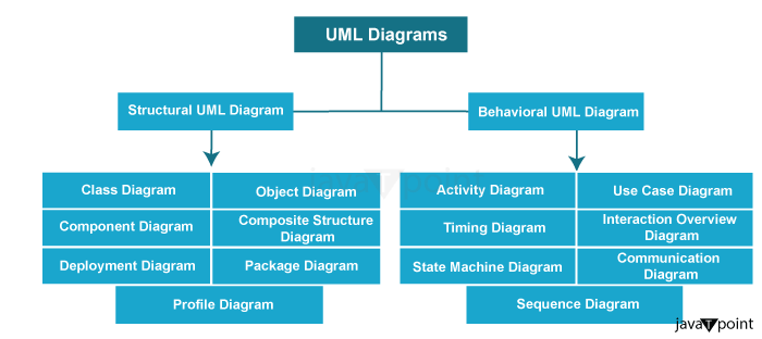
1. Behavioral UML DiagramsThe system can have two things, and these two things are static and dynamic elements. These two things give the result as the model is completed. We can also keep the dynamic character of the system with the help of a behavioural diagram. If we are going to change any part of the system, then it is known as the dynamic aspect. i. Activity DiagramWith the help of an activity diagram, we can deprecate the flow of control of the system. We can do this with the service of links and activities. The information that flows may be sequential, concurrent, or branching. We can call the movement as the system function. We can also deprecate the whole flow of the system by creating a large number of activity diagrams. Also, with the help of an activity diagram, we can visualize the flow of the control of the system. With the help of the chart below, we will understand how the ATM system works. 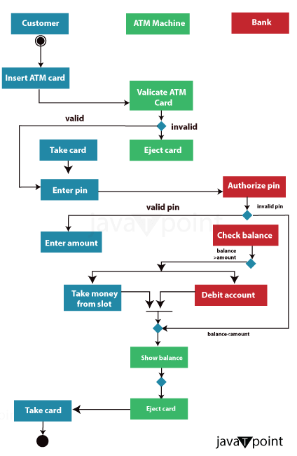
ii. Use Case DiagramWe can say that a use case diagram is the collection of cases, actors, and their interrelationships. With the help of this, we can also represent the use case view. The use case diagram can represent the functionality of a specific system. Also, we can describe the interaction between features and their internal/external controllers with the help of a use case diagram. We can refer to these types of controllers as actors. The below figure represents the use case diagram for an online shopping system. 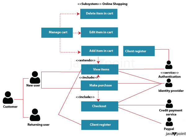
iii. Timing DiagramWhen our primary focus is on time, then with the help of this diagram, we can represent the relationships between objects. If we don't want to understand how the things are changes Then, we want to portray how these items, like actors, would act along a linear time axis. iv. State Machine / State Chart DiagramAny internal or external events are responded to with the help of any real-time system. If the state of the design changes, then these events are going to be accountable. We can also use the state chart diagram to show the event-driven state change of the system. It is essential to change the state of a class, interface, etc. The reaction of the internal or external variable can be deprecated with the help of a state chart diagram. The below figure describes the graph of the state machine diagram. 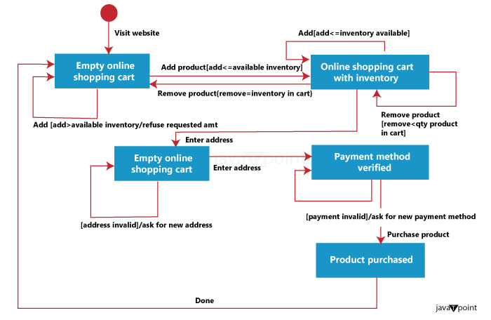
v. Communication DiagramWe can also use the communication diagram as a sequential diagram. These are also known as the interaction diagram. These diagrams show the interaction of the things in the object. It is also an object diagram for extinction, which can deprecate the message with the entity that goes from one to another. The below figure explains the sample communication diagram. 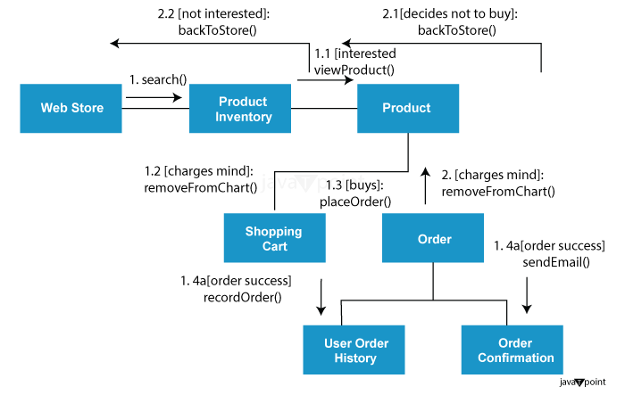
vi. Sequence DiagramThe sequence diagram is a type of interaction diagram. The chart's name also shows that maybe it has some sequences, which are messages moving from one item to another. If we talk about the execution and implementation, the interaction between the system's components is critical. We can use a sequence diagram to decrypt the series of calls made by the system that is used to perform the given function. The below image shows the sequence of the online shopping system. 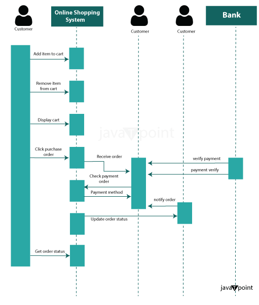
2. Structural UML DiagramsWe can decrypt the system's structure with the help of Structural UML Diagrams. The system's structure includes classes, objects, packages, components, and so on, as well as the relationships between those parts. i. Class DiagramThe class diagram is one of the most common UML diagram types. It is also known as the foundation of all object-oriented software systems. It is also used to illustrate the static structure of the system. It also provides the identification of the relationship between various objects and classes. The class diagram is represented with the help of Classes, interfaces, relationships, and collaboration. We can also depict the essential representation of the static representation of the system. The below image represents the class diagram for an ATM management system. ii. Object DiagramWe can describe the object diagram with the help of a class diagram. So, this diagram represents real-world objects according to the design of the software. We can say that the object diagram is the collection of the same items within the same relationship, similar to the class diagram. They are also used to represent the static view of the system. We can use the object diagram identical to the class diagram. It has an exception, and the exception is that we can use this to create the prototype of the system. The below figure represents the object diagram of the ATM. 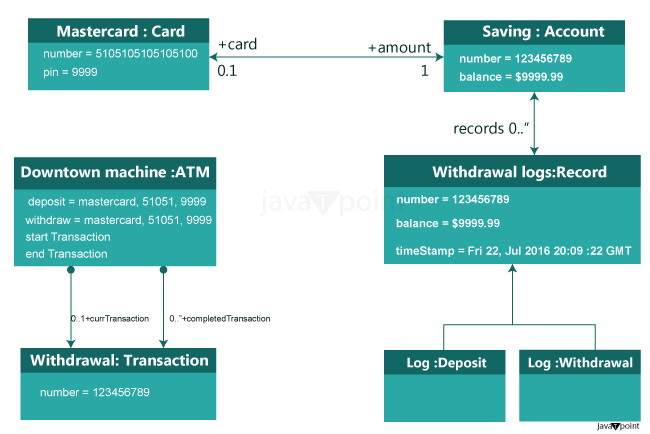
iii. Component DiagramWe can describe the group of components and the connection between them with the help of a component diagram. Some examples of the component diagram are Classes, interfaces, and collaborations. We can also explain the view of the implementation of the system with the help of a component diagram. We can organize the artefacts of the software, such as classes, interfaces, and so on, into groups based on their relationship during the design phase. We can also call these groups as components. We can also implement the visualization with the help of a component diagram. The below image represents the component diagram of the library management system. 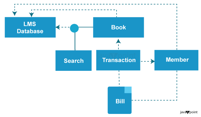
iv. Composite Structure DiagramWe can also say these diagrams are the blueprint of the internal structure of the classifier. With the help of these Composite Structure Diagrams, we can explain the collaboration of the classifier and its interaction with its environment through the ports. They can quickly represent any hardware's internal components to better understand its inner workings. 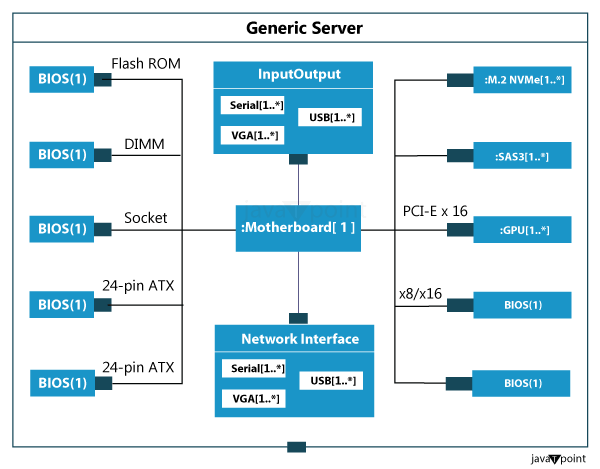
v. Deployment DiagramWe can create the deployment diagram with the help of nodes and their connection. Also, these nodes are called the entity of the house of the component. With the help of a deployment diagram, we can explain the view of the system's deployment. The employees are also known as the deployment team. Below is a sample example of the deployment diagram. 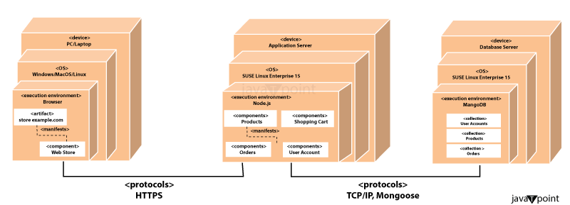
vi. Package DiagramThe macro container is represented as the package diagram, which requires the deployment of the UML diagram in it. Also, different packages contain the nodes and artefacts. In that package diagram, all the things grouped into components and models similar to the namespace might somehow encapsulate many connected names. Below the image is a sample package diagram. 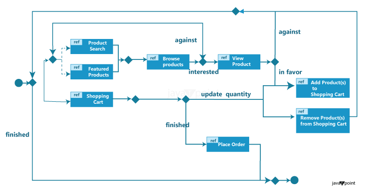
vii. Profile DiagramIn the UML diagram, the profile diagram is not in a form of conventional form. It is an extensible tool other than any diagram. We can also alter and extend the existing UML diagram with the help of stereotypes, restrictions, and tagged values. On the other hand, the profile diagram is like the language. For example, we can create a new sentence if someone speaks in English. Similarly, you can quickly and precisely build unique characteristics and semantics for UML diagrams if you talk about profile diagrams. ConclusionWe can say that the UML diagram is a type of graphical modelling language that is used in the field of software engineering. We can specify, visualize, build, and document the software system's artefacts (primary elements). With the help of a UML diagram, we can explain many types of operations in a specific format. We can also classify the UML diagram into structural and behavioural diagrams.
Next TopicDesign Patterns in Software Engineering
|
 For Videos Join Our Youtube Channel: Join Now
Feedback
- Send your Feedback to [email protected]
Help Others, Please Share


