| |

De-MultiplexersA De-multiplexer (De-Mux) can be described as a combinational circuit that performs the reverse operation of a Multiplexer. A De-multiplexer has a single input, 'n' selection lines and a maximum of 2^n outputs.The following image shows the block diagram of a 1 * 4 De-multiplexer. 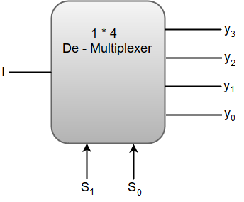 The function table for a 1 * 4 De - Multiplexer can be represented as:
From the above function table, we can write the Boolean function for each output as: y3 = S1S0 I, y2 = S1S0' I, y1 = S1' S0 I, y0 = S1'S0' I The above equations can be implemented using inverters and three-input AND gates. 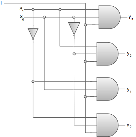
We can also implement higher order De-multiplexers using lower order De-multiplexers. For instance, let us implement a 1 * 8 De-multiplexer using 1 * 2 De-multiplexer in the first stage followed by two 1 * 4 De-multiplexers in the second stage. The function table for a 1 * 8 De-multiplexer can be represented as:
The block diagram for a 1 * 8 De-multiplexer can be represented as: 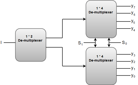
The Selection lines 'S1' and 'S0' are common for both of the 1 * 4 De-multiplexers.
Next TopicRegisters
|
 For Videos Join Our Youtube Channel: Join Now
Feedback
- Send your Feedback to [email protected]
Help Others, Please Share


