Javatpoint Logo
Javatpoint Logo

Full - Adder

This circuit needs three binary inputs and two binary outputs. The truth table for a full-adder is:

Full - Adder
  • Two of the input variable 'x' and 'y', represent the two significant bits to be added.
  • The third input variable 'z', represents the carry from the previous lower significant position.
  • The outputs are designated by the symbol 'S' for sum and 'C' for carry.
  • The eight rows under the input variables designate all possible combinations of 0's, and 1's that these variables may have.
  • The input-output logical relationship of the full-adder circuit may be expressed in two Boolean functions, one for each output variable.
  • Each output Boolean function can be simplified by using a unique map method.

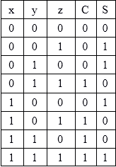
Maps for a full-adder:

Full - Adder

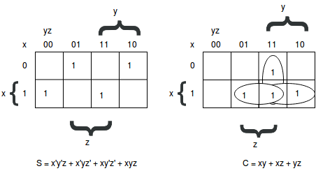
The logic diagram for a full-adder circuit can be represented as:

Full - Adder
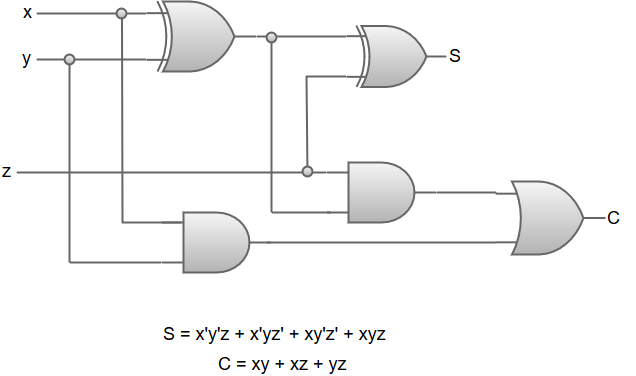
Next TopicS-R Flip-Flop


Youtube For Videos Join Our Youtube Channel: Join Now

Feedback


Help Others, Please Share

facebook twitter pinterest

Learn Latest Tutorials


Preparation


Trending Technologies


B.Tech / MCA