| |

EncodersAn encoder can also be described as a combinational circuit that performs the inverse operation of a decoder. An encoder has a maximum of 2^n (or less) input lines and n output lines. In an Encoder, the output lines generate the binary code corresponding to the input value. The following image shows the block diagram of a 4 * 2 encoder with four input and two output lines. 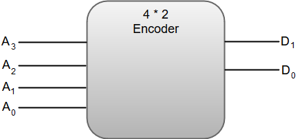 The truth table for a 4-to-2 line encoder can be represented as:
From the truth table, we can write the Boolean function for each output as: D1 = A3 + A2 D0 = A3 + A1 The circuit diagram for a 4-to-2 line encoder can be represented by using two input OR gates.  The most common application of an encoder is the Octal-to-Binary encoder. Octal to binary encoder takes eight input lines and generates three output lines. The following image shows the block diagram of an 8 * 3 line encoder. 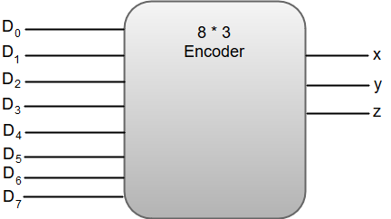 The truth table for an 8 * 3 line encoder can be represented as:
From the truth table, we can write the Boolean function for each output as: x = D4 + D5 + D6 + D7 y = D2 + D3 + D6 + D7 z = D1 + D3 + D5 + D7 The circuit diagram for an 8 * 3 line encoder can be represented by using two input OR gates. 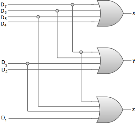
Next TopicMultiplexers
|
 For Videos Join Our Youtube Channel: Join Now
Feedback
- Send your Feedback to [email protected]
Help Others, Please Share


