| |

MultiplexersA Multiplexer (MUX) can be described as a combinational circuit that receives binary information from one of the 2^n input data lines and directs it to a single output line. The selection of a particular input data line for the output is decided on the basis of selection lines. The multiplexer is often called as data selector since it selects only one of many data inputs. Note: A 2^n-to-1 multiplexer has 2^n input data lines and n input selection lines whose bit combinations determine which input data are selected for the output.The following image shows the block diagram of a 4 * 1 Multiplexer. 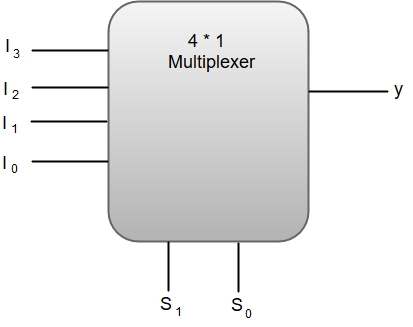 Out of these four input data lines, a particular input data line will be connected to the output based on the combination of inputs present at these two selection lines. Note: A truth table describing the circuit needs 64 rows since six input variables can have 2^n binary combinations. This will result in an excessively long table. Therefore, a more convenient way to describe the operation of multiplexers is using a function table.The function table for a 4 * 1 Multiplexer can be represented as:
From the function table, we can write the Boolean function for the output (y) as: y = S1'S0'I0 + S1' S0'I1 + S1S0'I2 + S1S0I3 The above equation for output 'y' can be implemented using inverters, three-input AND gates and an OR gate. 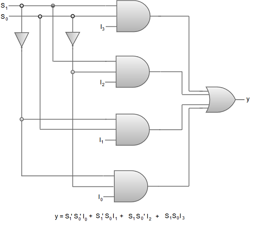 We can also implement higher order multiplexers using lower order multiplexers. For instance, let us implement an 8 *1 multiplexer using two 4*1 multiplexers and a 2*1 multiplexer. The two 4*1 multiplexers are required in the first stage to get the eight input data lines. A 2*1 multiplexer is required in the second stage to converge the outputs generated at first stage into a single output. The following image shows the block diagram of an 8*1 multiplexer designed using two 4*1 multiplexers and a single 2*1 multiplexer. 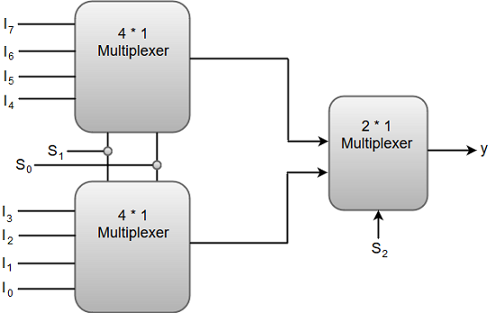 A set of common selection lines (S1 and S2) are applied to both of the 4*1 multiplexers. The output generated by both of the 4*1 multiplexers is applied as inputs of the 2*1 multiplexer. The function table for an 8*1 multiplexer can be represented as:
Next TopicDe-Multiplexers
|
 For Videos Join Our Youtube Channel: Join Now
Feedback
- Send your Feedback to [email protected]
Help Others, Please Share


