| |

Simplified Instructional Computer (SIC)SIC is a type of hypothetical computer, which contains some hardware features. Real machines are most often containing these features. The simplified instructional computer basically has two versions, i.e.,
1. SIC machine Architecture/componentsThe simplified instruction computer contains a lot of components, which are described as follows: MemoryThe memory in a simplified instructional computer is organized as a sequence of 8-bit bytes (1 byte = 8 bits). A word can be formed by 3 consecutive bytes (1 word = 24 bits). This means that with the help of 24 bits, the simplified instructional computer is designed. The lower number byte is used to address a word, and the addressing starts by 0 byte. A computer memory contains 215 bytes. 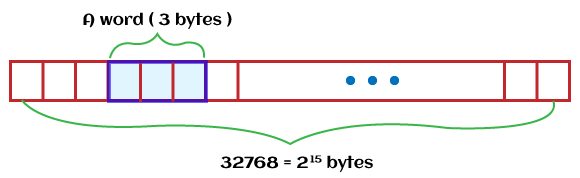
RegistersThe simplified instruction computer contains 5 types of registers. There is an address associated with every register, and that address is known as the register number. Each register can contain only 3 bytes that mean its size is 3 bytes. The size of the integer depends on the size of a register. There is no stack in the SIC, and it basically stores the address with the help of linkage register. If we want to write the recursive program, it is very difficult in SIC. If we write a function call with more than one layer, the programmer is required to maintain memory for return addresses.
There are five types of status word register, which is described as follows: Mode: The supervision mode (value = 1) or user mode (value = 0) are referred by this mode bit. 1 bit is occupied by the mode bit. [0] State: In this, we will see whether the process is in an idle state (value = 1) or running state (value = 0). 1 bit is occupied by the State bit. [1] Id: The process id (PID) is referred by the id bit. 3 bits are occupied by the Id bit. [2-5] CC: The condition code is referred by CC bit. The means the CC bit will show whether the device is ready or not. 2 bits are occupied by the CC bit. [6-7] Mask: The interrupt mask is referred by the mask bit. 4 bits are occupied by the mask bit. [8-11] X: The unused bits are referred by the X. 4 bits are occupied by the X. [12-15] ICode: The interrupt code is referred by the ICode. The remaining bits are occupied by the ICode. [16-23] Data format
Instruction FormatThere is a total 24-bit format contained by all instructions in a simplified instructional computer. The memory size of a simplified instructional computer is 215sup bytes. 
In this image, X is used to show the index address mode. Addressing Mode:The SIC can only support 2 modes, which are described as follows:
If X = 0, it will show the direct addressing mode. If X = 1, it will show the indexed addressing mode, which is shown as follows:
Here the content of register is shown by the (). Instruction Set:The instruction set in SIC is described as follows: Arithmetic Instruction: SIC uses memory and register A to perform the operations. With the help of register, the result will be stored. The arithmetic instructions are represented with the help of ADD, MUL, SUB, DIV, etc. For example: Examples of arithmetic Load and Store Instruction: It is used to store or move the data from memory to accumulator or from the accumulator to memory. The load and store instructions are represented with the help of LDX, STA, LDA, STX, etc. For example: Comparison Instruction: It is used to compare the contents in register A and the data in memory. It uses the CC (conditional code) of SW to save the result. The comparison instruction is represented with the help of COMP. For example: Subroutine Linkage Instruction: It is used to show the instruction which is related to the subroutine. The subroutine linkage instructions are represented with the help of RSUB, JSUB. Here, RSUB will be returned with the help of jumping the address in register L, and JSUB is used to jump and place the return address in L. Conditional Jump Instruction: It is first used to compare the contents of memory and accumulator. After that, on the basis of the condition, it will perform the task. The condition jump instructions are represented with the help of JLT, JGT, and JEQ. For example: Input and OutputAn 8 bits address is contained by each device. In the form of a single byte, the data is transferred to or from the rightmost byte of register A. The input and output instructions are of three types, which are described as follows: Test Device (TD): It uses the status word and conditional code to test whether the device is ready to send or receive a byte of data. If CC (conditional code) is <, in this case, the device will be ready. If CC is >, in this case, the device will be busy. Read Data (RD): With the help of RD, a byte can be read from the device. That byte will be stored in register A. Write Data (WD): With the help of WD, a byte can be written into the d specified by memory device from register A. Example of I/O for SIC 2. SIC/XEThe SIC/XE is an advanced version of SIC (simplified instructional computer), which stands for Extra Expensive or Extra Equipment. The SIC (simplified instructional computer) and SIC/XE are both upward compatible because they are closely related to each other. SIC/XE machine architecture/componentsThe SIC/XE contains a lot of components, which are described as follows: MemoryThe 8 bytes are usually contained by the memory. In SIC/XE system, the maximum available memory is 1 megabyte that means 220 bytes. The memory size of standard SIC is very small. Due to these memory size changes, the addressing mode and instruction format are changed in the simplified instructional computer extra expensive (SIC/XE). Just like the SIC, in the architecture of SIC/XE, a word (24 bits) can be formed with the help of 3 consecutive bytes. In SIC/XE, all the addresses are byte addresses. With the help of location of lower number bytes of a word, a word can be addressed. RegistersInstead of the registers of SIC (simplified instructional computer), there are 4 additional general-purpose registers in the SIC/XE. That means there are total 9 registers (4 additional registers + 5 registers of SIC). The four additional registers of SIC/XE are described as follows:
With the help of all 9 registers of SIC and SIC/XE, the easiest tasks are able to perform in a customized assembly language. The S and T registers can only be used for storing. We are not able to use these registers for the accumulator. For example: Data format:The data format of a SIC standard version and SIC/XE is almost the same. There are some differences in data formats, which are described as follows:
The SIC/XE contains an additional floating-point data type with 48 bit, which is shown as follows: 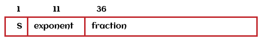
The value will be represented with the help of following formula: For example: Instruction format:The instruction format of simplified instructive format is not enough for SIC/XE because the available memory size of SIC/XE is 220 bytes. That means an address of SIC/XE cannot fit into the field of 15 bit. There are two ways to solve the memory-related problem, which is described as follows:
The SIC/XE contains four types of format. Where, format 1 and format 2 cannot be used to reference the memory. The bit 'e' is used to distinguish between format 3, and format 4. Format 1: It is a 1-byte format. For example: HIO, NORM, SIO, TIO. 
Format 2: It is a 2-byte format. 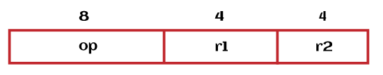
The registers are represented with the help of above two addresses. So we don't require to access the memory for execution. Format 3: It is a 3-byte format. 
The instruction will be interpreted in the form of simple SIC instruction if and only if "n bit" and "i bit" both bits are 0. Format 4: It is a 4-byte format. 
Here
The variation of the instruction can be interpreted with the help of the above-described bits alone or in combination, shown as follows:
So the last 15 bits, as well as the bpe bits, are treated as an address. Addressing ModesFor the format 3, the two new addressing modes are introduced in SIC/XE, which are described as follows:
If b bit and p bit both are set to 0 in format 3, the disp is taken in the form of a target address. This process is known as the direct addressing mode. With the help of direct, indirect, and relative addressing modes, and many other addressing modes, we can calculate the target address, which is described as follows: Base Relative addressing If we use the base relative mode, in this case, disp will be 12 bits unsigned integer. 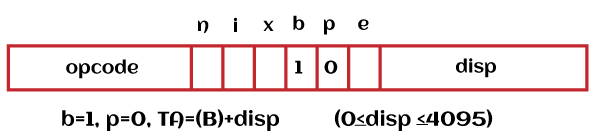
In this image, b stands for Base. Program Counter Relative If we use the program counter relative mode, in this case, disp will be 12 bits signed integer. 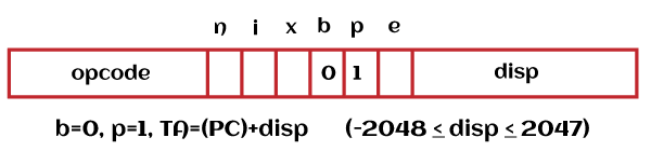
In this image, p stands for Program. Direct addressing In the direct addressing mode, the target address can be directly taken from the field of address or disp if and only if bits b and p are set to 0. 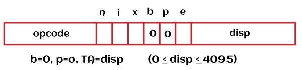
For format 3 and format 4 in direct addressing, the indication, target address, and calculation are described as follows: Indexed addressing The term (x) is added in indexed addressing to calculate the target address. If bit x is set to 1, in this case, the register X's value will be added in the calculation of a target address. 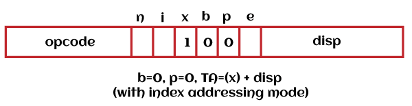
For format 3 and format 4 in direct indexed addressing, the indication, target address are described as follows: Format 3: n = 1, i = 1, x = 1, TA = (X) + disp Format 4: n = 1, i = 1, x = 1, TA = (X) + address Now we will see the use of target address with the help of bit i and n, which is described as follow:
The immediate indexing mode is described as follows: 
In this image, i stand for immediate. The indirect indexing mode is described as follows: 
In this image, n stands for indirect. The simple addressing mode is described as follows: Case 1: 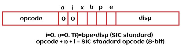
Case 2: 
Example of Addressing Mode
Instruction setThe instruction sets of SIC and SIC/XE are almost the same, but there is some additional instruction set in the SIC/XE because of the additional floating-point data format. So SIC/XE also provides a lot of additional instructions, including floating-point arithmetic instruction. All the additional instructions are described as follows:
The operations of floating-point arithmetic are described as follows: The operation of register move is described as follows: The operations of Register to register arithmetic are described as follows: The operation of supervision call is described as follows: The supervision call is used to generate an interrupt for OS (Operating system) The operations of Input/Output channel are described as follows: With the help of Appendix A, we are able to get the list of all instructions. The notations for appendix are described as follows: C: Conditional code CC P: Privileged instruction A ← (x. .x+2): It will move the word starting at x to A. X: This instruction is only available in SIC/XE Input and OutputThe SIC/XE provides the I/O channel. With the help of this channel, we can perform the operations of input and output while the CPU (Central processing unit) is executing the other instructions. It also allows the overlapping of input or output and computing. Due to this overlapping, the architecture of SIC/XE has become more effective. The instruction sets of I/O are SIO, TIO, and HIO, which have the ability to start, test, and halt the operations of I/O channel, respectively. |
 For Videos Join Our Youtube Channel: Join Now
Feedback
- Send your Feedback to [email protected]
Help Others, Please Share


