Command line in SolidWorks
The optional add-in SolidWorks 2D Emulator replicates the 2D CAD software command line. The emulator's counterpart to SolidWorks' drawing tools is the following commands:
- Entities in 2D CAD drawings (POINT, LINE, ARC, and so on)
- Other sketching instruments (FILLET, CHAMFER, DIM, and so on)
- See resources (PAN, VIEW, ZOOM)
- Entity attributes (COLOR, and so on)
- Information (LIST, and so on) (LIST, and so on)
- Feature development (EXTRUDE, REVOLVE)
- System utilities (ALIGN, PLOT, and so on)
By choosing SolidWorks 2D Emulator from the list of add-ins under Tools > Add-Ins, you may activate the 2D Command Line Emulator. When you open a document, the command line shows at the bottom of the screen.
Click Tools > Add-Ins and uncheck the SolidWorks 2D Emulator check box to disable the emulator.
You have the option to show or conceal the command line while working in a SolidWorks document with the 2D Emulator selected. Select 2D Command Emulator under View. The command line is displayed when a menu item has a check mark next to it. Click Help > 2D Command Emulator Help or enter Help on the command line to obtain help for the 2D Command Line Emulator.
The following are other techniques to modify the SolidWorks environment:
- Create your own keyboard shortcuts
- Make shortcut bars your own
- individualize menus
- personalize the toolbars and tools
- Create work flow-specific toolbars, menus, and the SolidWorks Resources tab.
- Create and save your own macros.
- Set choices
- adapt writing guidelines
Establishing Lines
To create lines in a drawing, use the Line command.
To build a line or a network of linked lines:
- Choose Draw > Line (or type Line).
- Type the following in the graphics area:
- A place where the line segment begins.
- A place where the line segment ends.
- Specify the following segment at this point, or simply press Enter to complete the picture.
In a group of linked lines, each segment exists independently. The Line command can also be used to add Lines to Arcs or Lines that already exist.
Taking back a line segment
- Windows: Type Undo or press Ctrl + Z.
- MacOS: Indicate the Undo choice.
How to finish a line drawing
- Choose Close from the menu.
To add a line segment to a line or arc already present:
- Choose Draw > Line (or type Line).
- Enter the key.
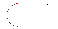
The end of the last line or arc you created is where the continuation line is attached.
- To specify the added line segment, click a point, then press Enter.
Access
- Order: Line
- Draw > Line on the menu.
Developing Rays
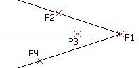
A Line that keeps going forever in one direction from its start is called a Ray. Rays may be used to create grids or frames from which you can build drawings.
To build a Ray or many Rays:
- Select Ray > Draw (or type Ray).
- Set the following in the graphics area:
- The beginning of Ray.
- Ray's first motion.
- Press Enter to define more Rays via the same origin using different through points.
In different Layers that you may turn off or freeze before printing, draw Rays. Alternatively, when the design is finished, remove Rays.
Access
Order: Ray
Drawing > Ray
Building infinite lines
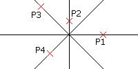
Infinite Lines are a collection of one or more construction lines that, starting at an origin, stretch forever in both directions.
To design frameworks or grids for use in drawing construction, utilize Infinite Lines.
To create a single or several Infinite Lines:
- Select Infinite Line under Draw (or type Infinite Line).
- Set the following in the graphics area:
- The Infinite Line is in the middle.
- To establish the initial Infinite Line direction, use a through point.
- Press Enter to establish more Infinite Lines via the same origin using different through points.
Create different layers using Infinite Lines that you may turn off or freeze before printing. Alternately, when drawing is finished, remove Infinite Lines.
Horizontal Infinite Lines are made by:
- Select Infinite Line under Draw (or type Infinite Line).
- Choose Horizontal from the menu.
- Type the following in the graphics area:
- a marker points for the line's location.
- Press Enter or more points to construct parallel horizontal lines.
Vertical Infinite Lines are made by:
- Select Infinite Line under Draw (or type Infinite Line).
- Choose Vertical from the menu.
- Specify a point to define the location of the line in the graphics area.
- Press Enter or more points to construct parallel vertical lines.
- Infinite Lines must be drawn in parallel and at an angle to one another.
Select Infinite Line under Draw (or type Infinite Line).
- Indicate the Angle choice.
- Input a value for the angle in the designated angle drawing units by typing it in, or use the Reference option to pick a reference object, then enter the angle from that entity.
- The Infinite Line appears in relation to the horizontal or the given object at the defined angle.
- Specify a point to define the location of the line in the graphics area.
- Press Enter or more points to define parallel lines.
A vertex can be used to produce bisecting infinite lines:
- Select Infinite Line under Draw (or type Infinite Line).
- Give the Angle Bisect option some details.
- Type the following in the graphics area:
- A vertex location definition point.
- The location where the Infinite Line's initial angle can be defined.
- The point to provide the second angle that establishes the Infinite Line bisecting the vertex.
- Press Enter or more points to define further bisecting Infinite Line
Infinite Lines must be offset from other linear entities in order to be created:
- Select Infinite Line under Draw (or type Infinite Line).
- Enter the Offset option's value.
- Enter the offset's length.
- The graphics section:
- Pick an entity with a linear source.
- Indicate where the Infinite Line is.
- Either hit Enter or repeat step 4.
You can use the Specify Position option, choose a linear source entity, and click a point in the graphics area to establish the offset distance instead of carrying out steps 3 and 4.
Access
The Infinite Line commands
Draw > Infinite Line on the menu
Creating Entity Offsets
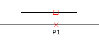
Create parallel forms of Lines, 2D Polylines, Circles, Arcs, Ellipses, Elliptical Arcs, Splines, Rays, and Infinite Lines by using the Offset command. A duplicate of a chosen entity is positioned a certain amount of distance away from the original object. The original thing remains put.
Depending on the sort of drawing entity, the offset may be:
- Lines: Produces duplicates and advances the specified distance and direction.
- Circles, arcs, and ellipses: Copies are made and scaled using the entity's centre as a starting point. Circles and arcs can be formed with radii that are either smaller than or bigger than that of the initial entities.
To construct entity offsets:
- The Modify > Offset button (or type Offset).
- Enter the offset between the source and destination entities in terms of distance, or choose an option:
- Delete. When a copy of an entity is placed, the original entity is removed.
- Distances. Numerous offsets are produced. Click on the side of the thing you want to offset after choosing it. Put the first distance and second point in specifics. After that, you may specify further offsets.
- Layer of destination. Gives instructions on whether the object should be duplicated on the active layer or the source layer.
- To point through. A point you describe is used to create an offset entity going through it.
- Type of gap. To fill any potential gaps in offset polylines, provide the gap type:
- Arc. Fillets holes the offset distance is equal to the fillet radius.
- Chamfer. Gaps with chamfers the offset distance is equal to the perpendicular distance between each chamfer and its associated vertex on the source linear polyline segment.
- Natural. It extends projected intersections of linear polyline segments.
- Choose the object to offset.
- Use the Undo option to roll back the previous offset without ending the Offset command that is now running.
- To finish the command, either gives more offsets or the Exit option.
Access
- Order: Offset
- Modify > Offset on the menu
Entity Copies
To duplicate drawing entities and put a copy of them in a certain area, use the Copy command.
The replicated entities are identical replicas of the provided entities, containing the entity's shape as well as all entity characteristics like Layers, Line Colors, Line Styles, and Line Weights.
The cloned entities can optionally be forced onto the active layer.
You can make many copies of a single choice. You may also make a certain number of copies in a linear pattern. There are two approaches:
- Starting from a base point, make the required number of copies at the specified displacement.
- Make as many copies as necessary, equally spaced between the two given spots and moving in the direction indicated.
A useful tool for producing several copies in a linear or circular pattern is the Pattern command.
To duplicate drawing entities:
- To Modify > Copy (or type Copy).
- Enter after specifying the entities you want to replicate.
- Give the clone a source base point.
- or -
Provide the relative location of the copy by selecting the Displacement option and entering the X, Y, and Z displacements, for instance, 3, 5, 5. Do not mention a Z delta, such as 3, 5, if you simply wish to copy in the X and Y directions. After you specify the displacement with this option, the programme ends.
- Set a destination location to which the copy should be moved.
- or -
To push the entities onto the active layer, use the Active Layer option before specifying the destination location. Until you reset it, this configuration is kept for the current application session.
- You can select successive destination points to make additional copies.
The copies are positioned where they are required to be. If a multiple copy produces an unexpected outcome, choose the Undo option.
- Enter to complete duplicating entities.
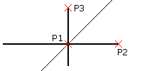
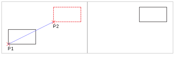
To determine the separation and direction of the duplicated entities from the original entity, you must give a base point (P1 in the picture) and a destination point (P2). It is not necessary to choose these locations on the first entity.
To make a linear pattern of a certain number of copies:
- To Modify > Copy (or type Copy).
- Enter after specifying the entities you want to replicate.
- Give the clone a source base point.
- Make a note of the Pattern choice.
- Indicate how many copies there are in the linear pattern.
- Tell us about the second point. The displacement vector is defined by two points.
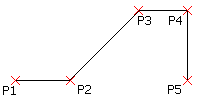
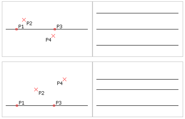
To indicate the distance (d) between the entities within the linear pattern and the direction of the linear pattern, you supply a base point (P1 in the picture) and a second point (P2). At the predetermined distance, the pattern's initial entity is produced (d). The displacement vector determines the direction and distance (d) at which further copies of the given item are positioned.
- Enter to complete duplicating entities.
Between two spots, make a certain number of copies by:
- To Modify > Copy (or type Copy).
- Enter to finish your selection after specifying the entities you wish to replicate.
- Give the clone a source base point.
- Make a note of the Pattern choice.
- Indicate how many copies there are in the linear pattern.
- Choose the Fit option.
- Tell us about the second point. The displacement vector is defined by two points.
- The distance (d) between the initial entity and the last entity of the linear pattern, as well as the direction of the linear pattern, are indicated by a base point (P1 in the picture) and a second point (P2). Between the two locations, there is an equitable distribution of the entities.
Access
- Order: Copy
- Copy from the menu.
Transient Entities
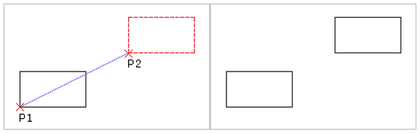
Reposition drawing entities inside the coordinate system with the Move command without altering their size or orientation.
Moving entities:
- To move, choose Modify (or type Move).
- Enter to confirm your choice of one or more entities to relocate after specifying them.
- Give the entities a base point and a target location, then move them by the given distance.
Instead, you may enter Displacement at the prompt and then enter the X, Y, and Z displacements to indicate the relative location of the duplicate. Do not give a Z delta if the motion will only be done in the X and Y axes.
As indicated, the entities relocate.
Access
- Order: Move
- Menu: Change > Move
- Context menu: Select entities, and then click Move with the right mouse button on the graphics area.
|

 For Videos Join Our Youtube Channel: Join Now


