| |

Move command in SolidWorksThe "Move/Copy Body" function in SOLIDWORKS is a quick and effective technique to appropriately reorient a model for a number of downstream usages. It may be necessary to rotate the model while dealing with imported geometry from STEP, IGES, or Parasolid. Your options for changing the orientation of the imported model are more restricted than they would be for a native SOLIDWORKS model. You can't try to solve it so quickly by changing the sketch plane of the first feature. Reorienting geometry to the default planes may be done using the 'Move/Copy Body' functionality. It will be simpler to find in assemblies as a result. The development of drawing views or the manufacture of Mould tooling can both benefit from reorienting a component. The "Move/Copy Body" function in SOLIDWORKS is a quick and effective technique to appropriately reorient a model for a number of downstream usages. It may be necessary to rotate the model while dealing with imported geometry from STEP, IGES, or Parasolid. Your options for changing the orientation of the imported model are more restricted than they would be for a native SOLIDWORKS model. You can't try to solve it so quickly by changing the sketch plane of the first feature. 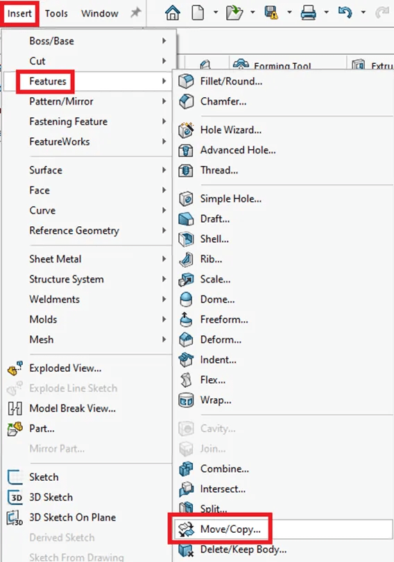
Reorienting geometry to the default planes may be done using the 'Move/Copy Body' functionality. It will be simpler to find in assemblies as a result. The development of drawing views or the manufacture of Mould tooling can both benefit from reorienting a component. 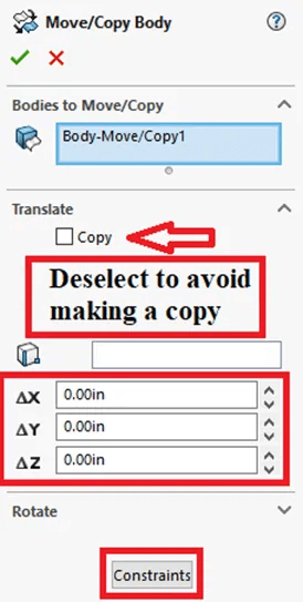
The two options for moving the bodies, Translate/Rotate or Constraints, are highlighted above in the lower two red boxes. Utilizing the normal assembly mates is quite similar to choosing the "Constraints" option. Three mates/constraints can completely specify the orientation of prismatic bodies, much like when mating components in assemblies. A sizable, orange triad that may be used to change the orientation of bodies is displayed when the Translate/Rotate option is selected (see illustration below). Dragging the arrows or circles or putting values into the dialogue boxes can be used to change the geometry. One step or feature can translate in several directions, however it is not possible to translate and rotate in the same feature. 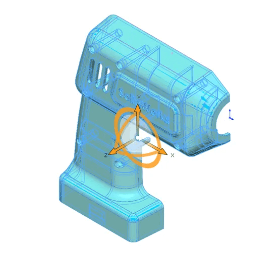
In this illustration, the origin is moved towards the bottom left-hand corner using the 'Constraints' option, three default planes, and a mix of geometric entities. The Right Plane and the lower back vertex are used in Step 1 as seen below. 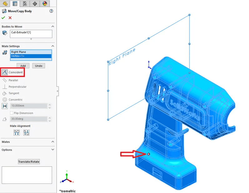
The model will be rotated 90 degrees in step 2. There are several methods for doing this. Using the 'Constraint' option with a bottom face to make it Coincident to the Top Plane is one naturally occurring method, as demonstrated below. 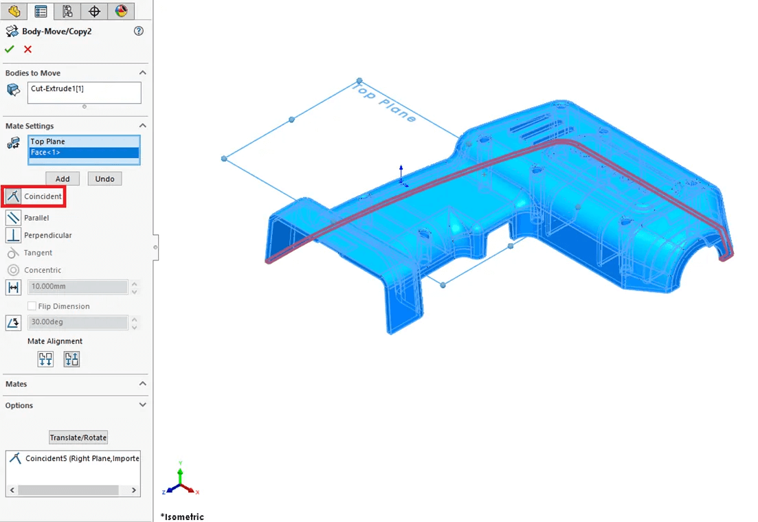
To lock in each constraint, remember to choose "Add" after adding each one. You can add many "Constraints" in the same command. The last step demonstrates how, like in a typical assembly mate, one of the restrictions might utilize the Origin as a point. The origin is positioned in the lower-left corner after this final action. 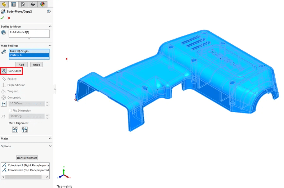
This step might have alternatively been accomplished using the Front Plane. In situations where a flat face is not always possible, vertices or edges might be employed. The third time you choose "Add," all three "Constraints" are locked into a single "Move/Copy Body" function. By choosing "Edit Feature," this feature, which functions as a point in time, may be changed. Move or Copy Body RestrictionsYou cannot translate and rotate in the same step or command while using the "Move/Copy Body" tool, as was already described. The good news is that these orientation shifts may be simply divided into a number of attributes. The final item to be aware of is that adding a mix of reference geometry as constraints to an imported part is not supported by "Move/Copy Body." Choose a vertex, edge, or face if you can if you get the warning "Please choose an entity from one of the moving bodies." An axis or reference plane cannot be used with another plane as a constraint. In other words, you can only utilise an edge, face, or vertex together with one reference plane. The worst-case situation would be to obtain the desired orientation by combining the constraint with translate/rotate "Move/Copy Body" capabilities. Another solution is to build a tiny extrusion, utilise a face, edge, or vertex from that geometry, and then cut or use the 'Delete Face' command to delete the superfluous geometry. ConclusionThe SOLIDWORKS "Move/Copy Body" capability may be used manually or through settings, and it can be used repeatedly. As previously indicated, this command duplicates geometry similar to the "Linear Pattern" function and is compatible with both solid and surface bodies.
Next TopicBreak command in Solidworks
|
 For Videos Join Our Youtube Channel: Join Now
Feedback
- Send your Feedback to [email protected]
Help Others, Please Share


