| |

Mirror command in Solid WorksMirroring capabilities You may mirror bodies, facial features, and faces in sections. You may mirror assembly characteristics in assemblies. To reflect a feature
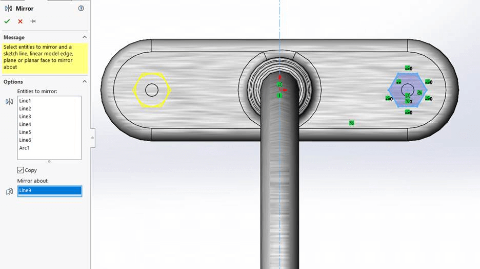
How to utilize the mirror tools in SOLIDWORKSThe totally associative nature of the outcomes not only expedites the initial design process, but also enables symmetrical design modifications. After all, a mirror is a kind of pattern; it only has one copy, which typically reflects the copied object. Let's begin with the very first step, the drawing In part design drawing, there are two mirror tools: Mirror Entities and Dynamic Mirror. Because it is simple to access on the command manager, Mirror Entities is the most popular. You launch the tool after creating the initial sketch entities. Using the mirror tool, which can be a sketch line, part edge, or plane, pick the sketch entities and copy from one side to the other. As a result, the newly generated entities and the original drawing points have a symmetric relationship. 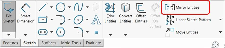
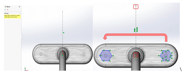
The fact that Dynamic Sketch is absent from the command manager makes it a tool that is less frequently utilized. If you find it useful, you may modify your command manager to add it. The first step in a dynamic sketch mirror is to create a line and designate it as a mirror tool in advance. Next, more sketch entities are added. When you add additional sketch material, the line will be marked with a doubled hashed line, which will dynamically copy and add symmetric entities to the other side of the line. A second tool selection will disable the dynamic mirror command. 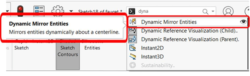
Since you will be able to link the two sets of sketch information to one another and the dimensions will now be symmetric, I advise adding your final relations and dimensions later. 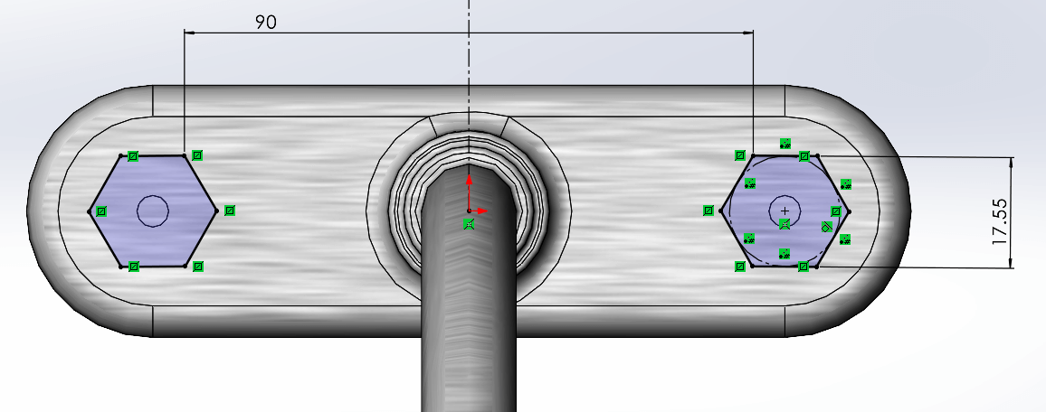
Here is the final product of our mirror-extruded tap handles with additional fillets. 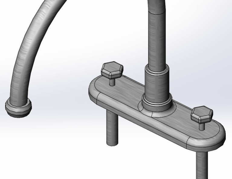
This technique, as you can see in the example above when features are placed in mirrored positions, works well for symmetric drawings of complex sections or modifications. Mirroring a feature or body is another way to introduce geometry changes in mirrored places. To enable mounting of this cabinet for our vanity, let's make some holes. 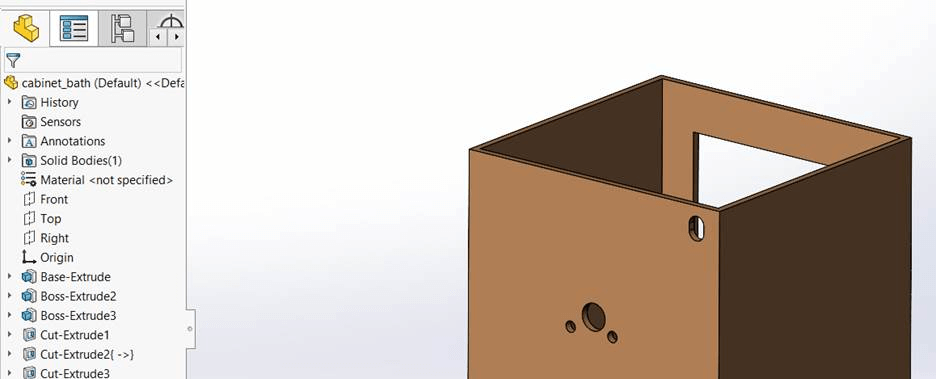
We may mirror this feature to the opposing sides of the component over the relevant reference planes by taking this last Cut-Extrude for the mounting hole. We can even add a second reference plane in SOLIDWORKS 2022, eliminating the need for a second mirror feature and allowing us to have four holes. 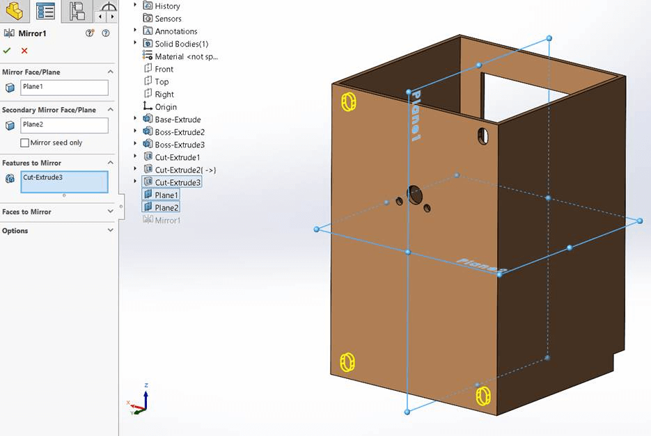
You can select to integrate the resultant bodies from body mirrors IF they contact or to produce separate bodies to keep using multiband modeling techniques. Please be aware that it is inappropriate to tick the "merge solids" option for bodies that do not contact. 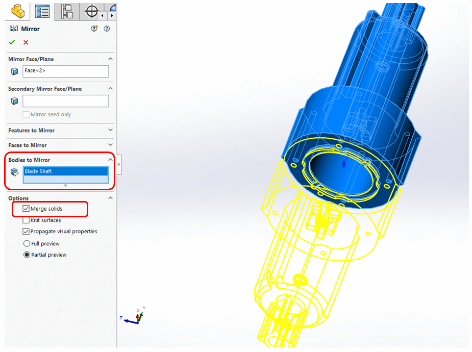
Let's see how an assembly with symmetrical pieces is put together last. Components might be mirrored to speed up final design assembly. A couple extra settings are available when mirroring components. I wanted to mimic the component location, as you can see, thus I chose a slightly different handle design. 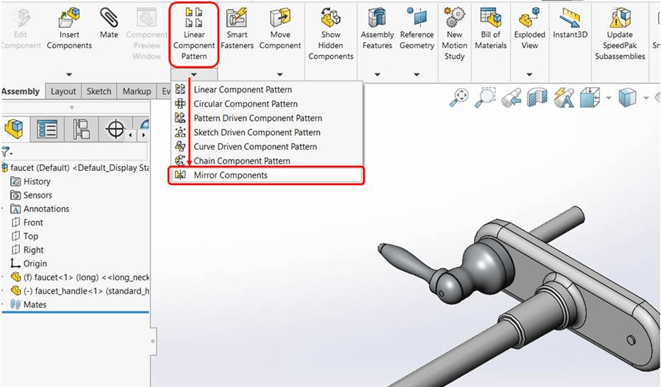
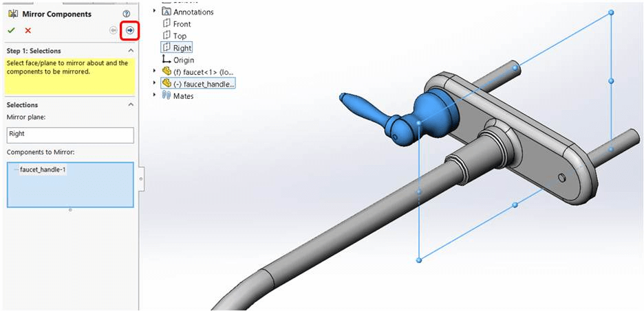
You will find options for your mirror on the next page. The simplest option for me to add a second instance of this handle is to move it up in my BOM listing and place it above the Right plane. 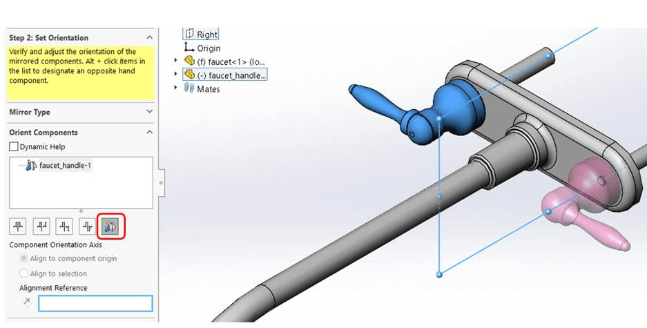
Based on orientation, there are also more choices available: In the end, you may even make a new configuration or new file based on the mirroring of the portion or parts in the opposite direction. In SOLIDWORKS, it is simple to produce opposite-hand copies of components.Engineers frequently require a component in the opposite-hand configuration. At the assembly level, the Mirror feature is a frequently utilised technique. When defining this feature, you have the option of creating an opposite-hand version. This is excellent, but occasionally you want to make a variant that is opposite-handed or without the need for an assembly. I want to demonstrate how to directly build opposite-hand replicas of parts in this tech blog. Utilizing the MirrorYou may make a part that is the mirror image of an existing component using the Mirror Part feature. The original version is automatically used to create the mirrored version. The two components will thus always match. Making a mirror image of a section
ConclusionAs we've seen, making an opposite-hand version of your component files is rather simple. Additionally, you can make these files beforehand rather than using the assembly mirror function. To avoid having to duplicate the flat pattern, it is a good idea to include the sheet metal information in the mirrored component for sheet metal parts.
Next TopicGrid command in Solid Works
|
 For Videos Join Our Youtube Channel: Join Now
Feedback
- Send your Feedback to [email protected]
Help Others, Please Share


