| |

Blinking an LEDIt is the simple basic project created using Arduino. LED (Light Emitting Diode) is an electronic device, which emits light when the current passes through its terminals. LED's are used in various applications. It is also used as an ON/OFF indicator in different electronic devices. In this project, we will connect the LED to the digital pin on the Arduino board. The LED will work as a simple light that can be turned ON and OFF for a specified duration. Structure of LEDAn LED is a two-terminal device. The two terminals are called as Cathode and Anode. It is shown below: 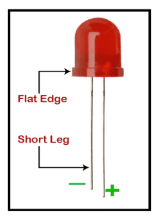
The long terminal is called Anode, and the shorter terminal is called Cathode. Here, cathode is the negative terminal and anode is the positive terminal. Components of the projectThe components used in the blinking of an LED are listed below:
We can use a resistor of any value upto 470 Ohms. We can use other value of resistors as well, depending on our circuit requirements. Usually, the value should not exceed the allowable forward current. Structure of the projectThe structure clearly shows the pinout of the UNO board. It also displays the LED and resistance connected to the board. It is shown below: 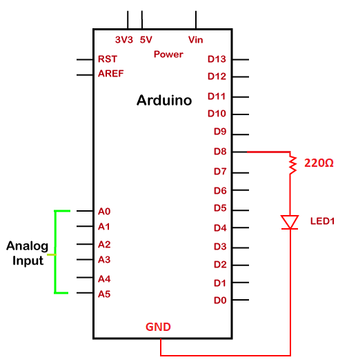
SketchWe need to install the Arduino IDE, to begin with the coding, which is already discussed. Open the IDE and start with the coding, which is given below: We can modify the delay duration according to our choice or as per the requirements. Every statement of coding is explained in Arduino coding basics. You can open the URL for clear understanding. Note: Make sure the code is free of errors.The sketch will be uploaded to the board after the correct compiling, as shown below: 
We are required to click on the Verify button to compile the code. The RX and TX LED on the board will light up after the successful uploading of the code. ProcedureThe procedure to join the components of the project is shown below:
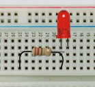
We can plug-in the LED anywhere on the breadboard.
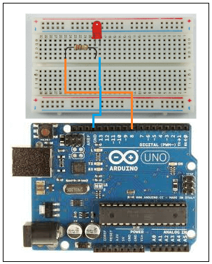
Here, the orange wire is connected to the PIN 8, and the blue wire is connected to the GND. The shorter terminal indicates the negative. So, we will connect the shorter terminal to the Ground (GND).
Important points The important points to be considered in this project are listed below:
The resistor prevents the excess current from reaching the LED. The excess current in the connection can burn the LED. Hence, a resistor in series with the LED is used in the connection.
Next TopicBlinking Two LED
|
 For Videos Join Our Youtube Channel: Join Now
Feedback
- Send your Feedback to [email protected]
Help Others, Please Share


