| |

Arduino PotentiometerThe potentiometer is a device that is used to measure the voltage or electric potential. It provides a variable resistance when the shaft of the device is turned. Here, we will measure the amount of resistance as an analog value produced by the potentiometer. We will connect the potentiometer to the Arduino UNO board and will measure the state of the potentiometer. The required code will be uploaded from our computer to the Arduino board. The variable resistance measured by the potentiometer can be easily read as an analog value into the Arduino board. What is Potentiometer?The potentiometer is a three-terminal device. It has a rotating contact that acts as an adjustable voltage divider. The potentiometer structure consists of a sliding contact (called wiper), a resistive element, electrical terminals, and a housing. The sliding contact moves along the resistive element, while the housing consists of the wiper and the element. Working: The fixed input voltage is applied across the two ends terminal of a potentiometer, which further produces the adjustable output voltage at the wiper or slider. As the slider moves from one end to another, the divider can vary the output voltage from maximum to Ground. The connection of potentiometer with Arduino board is shown below: 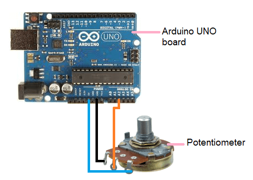
The middle terminal of potentiometer is connected to the analog pin to read the analog data. Potentiometer with LEDIn this example, we will use a potentiometer that controls the value at which LED blinks. Hardware Required The required components are listed below:
Connection
Procedure The analog input will turn the LED ON and OFF, which is connected to the pin number 13 of the Arduino UNO board. The time (delay time) at which LED is ON/OFF depends on the value acquired by the analogread( ). We have connected the potentiometer to the analog pin number 2 of the Arduino UNO board. When the shaft is turned, the amount of resistance on either side of the potentiometer changes. The distance between the pin connected to 5V and GND gives the analog input. We read input 0 when the shaft is turned in one direction, while we read input 1023 when the shaft is turned in another direction. In between the turning input between 0 and 1023, we get the desired value returned by the analogRead( ). It is proportional to the voltage being applied to the pin. Code We will now upload the code to the board. The code is given below: Connection diagram The connection diagram is shown below: 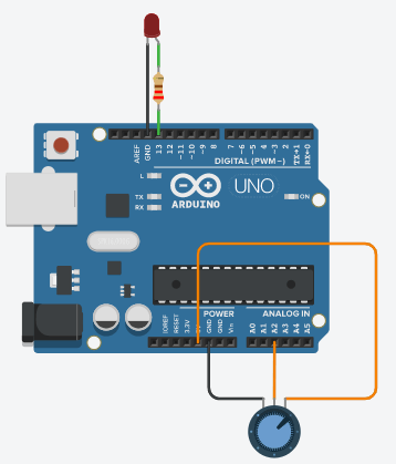
Next TopicArduino Interrupt
|
 For Videos Join Our Youtube Channel: Join Now
Feedback
- Send your Feedback to [email protected]
Help Others, Please Share


