| |

Arduino Due PinoutThe Arduino Due is based on the 32- bit ARM core. It is the first Arduino board that is developed based on the ARM Microcontroller. It has two ports, which are named as Native USB port and Programming port. The pinout of Arduino Due is shown below: 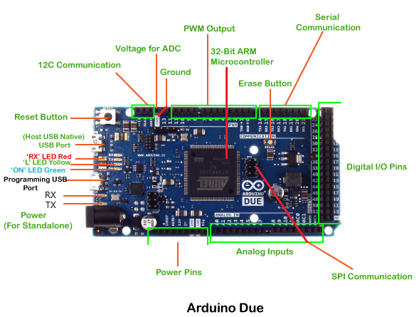
Let's discuss this in detail: RX and TX The successful flow of data is represented by the lighting of the TX and RX LED. Power Pins The power pins consist of GND (Ground), 5V, 3V3, Vin, and IOREF pins. GND: These are the ground pins, which are used to ground our circuit. 5V: The 5V pin works as the output regulated voltage of 5V. The power source of 5V for the Arduino Due board are USB connector, DC power jack, and the Vin. The power can be supplied to the board from either of the above-specified sources. 3V3: The 3V3 pin works as the output regulated voltage of 3.3V. It can provide power to the SAM3X Microcontroller. Vin: It is defined as the input voltage, which is applied to the Arduino Board when it is using an external power source. IOREF: It stands for Input-Output voltage REFerence. It allows the shields to check the operating voltage (3.3V or 5V) of the board. The shields are connected to the Arduino Board. The Microcontroller operates with the reference voltage provided by the IOREF. Analog Pins The pins numbered as Ao, A1, A2, A3, A4, A5, A6, A7, A8, A9, A10, and A11 are the analog pins. The function of Analog pins is to read the analog sensor used in the connection. It can also act as GPIO (General Purpose Input Output) pins. Digital pins There are 54 digital Input/Output pins. The digital pins have the value HIGH or LOW. The pins labeled from 0 to 53 are the digital pins. SPI Communication SPI stands for Serial Peripheral Interface, which is considered as a system for serial communication. It uses conductors for data receiving, data sending, synchronization, and device selection (for communication). It can communicate quickly over short distances. It is also used to communicate between the two Microcontrollers. I2C Communication The I2C (Inter-Integrated Circuits) is a serial communication protocol that uses SCL (Serial Clock) and SDA (Serial Data) to receive and send data between two devices. Voltage for ADC The ADC (Analog to Digital Converter) is used to map the voltage value to the integer value. The voltage from 0 to 5 is mapped into the integer value from 0 to 1023. ADC in Arduino Due is a 6-channel converter of 10-bit. Erase Button The on-board Erase button allows to erase the Flash Memory of the SAM3X. To erase, we need to on the power of the board and press and hold the Erase button for a few seconds. It will remove or erase the current sketch loaded in the MCU. Reset Button It is used to add a Reset button to the connection. To reset the Microcontroller, we need to press and hold the Reset button. USB Port It allows the board to connect to the computer. It is essential for the programming of the Arduino Due board. We usually plug the USB cable in the Programming port to load the sketch to the board. Programming USB port The programming port is connected to the high-performance 8-bit Microcontroller (ATMEL 16U2), which also acts as a USB to serial converter. Native USB port The Native port is directly connected to the SAM3X MCU. It uses the serial USB object to support the CDC (Communication Device Class) serial communication. Power Jack The adapter can be plugged-in into the power jack to connect it to the Arduino Due board. 32-bit ARM Controller The use of a 32-bit ARM Controller makes the board useful for large scale projects. The AC to DC adapter is mounted on it, which acts as a power source for the board. It is only consistent with the shields that are working at the voltage of 3.3V. It is based on the Atmel SAM3X8E ARM Cortex-M3 CPU. PWM Output The PWM (Pulse Width Modulation) pins are used to convert the digital signal into the analog signal. The pin labeled from 2 to 13 can be used as the PWM output pins. Serial Communication The serial port is also known as the UART port. It uses the USB port to communicate with the computer. It is also used to communicate on the transmitting LED called TX and RX.
Next Topic#
|
 For Videos Join Our Youtube Channel: Join Now
Feedback
- Send your Feedback to [email protected]
Help Others, Please Share


