Arduino LDRArduino LDR (Light Dependent Resistor) project uses the photoresistor to light an LED. The LED will light up whenever there is dark or no light over the sensor. What is photoresistor? It is defined as a light-controlled resistor, which is also called as LDR. It is a variable resistor that controls the resistance in accordance with the received light intensity. It means, the resistance decreases as intensity of light increases. Let's start with the project. Hardware RequiredThe components required for the project are listed below:
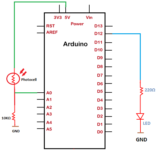
We can use any color LED as per our choice. Structure of the projectThe structure of the project is shown below: 
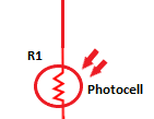
How to calculate the output voltage using photoresistor? The structure of photoresistor is shown below: 
The formula to calculate the dark output voltage is given below: 
where, Vin = 5V Vout = Output voltage Here, R2 is the resistance connected in series with the photoresistor = 10K Ohm. R1 is the resistance of the photoresistor. Note: The resistance decreases with increasing light. Hence, the output voltage will increase. It means that the output voltage calculated at the light will be higher than the output voltage calculated at dark.Here, dark and light specify the light falling on the sensor. ConnectionThe connection of the above project is discussed below:
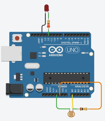
Note: We have connected the LED only to enhance the project. We can also create the project without using the LED. It will not impact the output.SketchConsider the below code: Connection DiagramThe connection diagram is shown below: 
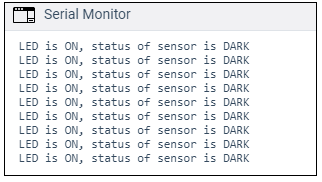
Output The output on the serial monitor will appear as: 
LED is one because there is dark over the sensor.
Next TopicArduino Accelerometer
|
 For Videos Join Our Youtube Channel: Join Now
Feedback
- Send your Feedback to [email protected]
Help Others, Please Share


