| |

Arduino Micro PinoutThe Arduino Micro is based on the ATmega32U4 Microcontroller with the inbuilt USB. The Micro can also appear as a mouse or keyboard when connected to the computer. It uses Micro USB B cable. The pinout of Arduino Micro is shown below: 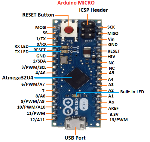
Let's discuss each pin in detail.
It is the low power 8-bit Microcontroller with the 2.5KB SRAM, 32KB Flash memory, and 1KB EEPROM. The operating voltage lies between 2.7 and 5.5V. It is a 12 channel 10-bit Analog to Digital converter. The 16Mhz clock oscillator is used by the microcontroller to achieve the 16 MIPS (Millions Instructions Per Second) throughput.
It stands for Slave Select. It is the Slave Select line, which is used by the master. It acts as the enable line.
The ground pins are used to ground our circuit.
The pin numbered as 2 is the SDA pin. It is the data line. We need to use a pull-up resistor while connecting the SDA pin.
The Analog Reference (AREF) pin is used to feed a reference voltage to the Arduino Micro board from the external power supply.
The pin numbered as 3 is the SCL pin. It is the clock line. We need to use a pull-up resistor while connecting the SCL pin.
It stands for Master In/ Slave Output. The slave line in MISO is used to send data to the master.
It stands for Master Output/ Slave Input. The slave line in MOSI is used to send data to its peripherals.
The SCK stands for serial clock. In slave, it works as the input of the clock generator. In master, it works as the output clock. The data generated by the master is synchronized by the SCK.
The PWM (Pulse Width Modulation) pins are used to convert the digital signal into the analog signal. It is commonly used when the built-in DAC (Digital to Analog Converter) is absent on the Arduino board. The pins numbered as 3, 6, 9, 10, 11, and 13 are the PWM pins.
It allows the board to connect to the computer. It is essential for the programming of the Arduino Micro board.
The program or firmware with the advanced functionalities is received by microcontroller with the help of the ICSP (In-Circuit Serial Programming) header. The ICSP header consists of 6 pins. The structure of the ICSP header is shown below: 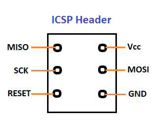
It is the top view of the ICSP header.
The function of Analog pins is to read the analog sensor used in the connection. It can also act as GPIO (General Purpose Input Output) pins. There are 12 analog pins labeled as Ao, A1, A2, A3, A4, A5, A6, A7, A8, A9, A10, A11.
The pins numbered as 4, 6, 8, 9, 10, and 12 are the digital Input/Output pins. The digital pins have the value HIGH or LOW.
It is used to add a Reset button to the connection. To reset the Microcontroller, we need to press and hold the Reset button.
The successful flow of data is represented by the lighting of the TX and RX LED. The Serial 1 (TX) and Serial 0 (RX) is used to transmit and receive the TTL serial data using the serial capability of the Arduino ATmega32U4 hardware.
The Input Voltage (Vin) is applied as the input voltage to the Arduino board from an external power source. We can also access the power jack voltage through this pin.
The Vcc is the voltage supplied to the ATmega32U4 on board. It also depends on the version of the board used.
Next TopicArduino Due Pinout
|
 For Videos Join Our Youtube Channel: Join Now
Feedback
- Send your Feedback to [email protected]
Help Others, Please Share


