| |

Arduino Servomotor using PotentiometerThe Potentiometer will be used to control the position of the servo motor. The connection will be similar to the last servo motor project, except the added Potentiometer. Let's start with the project with Arduino. Hardware RequiredThe components required for the project are listed below:
Mini Servo Motor: It is defined as a tiny motor that can approximately rotate up to 180 degrees. It works similar to the usual servo motor, but smaller in size. PrincipleThe project allows us to control the shaft at angles between 0 and 180 degrees. We can also set the rotation of the shaft at different speeds. Servo motor has three terminals signal, power, and ground. The power pin of the servo motor is connected to the PWM pin of the Arduino board. Here, we have connected the power terminal to pin 9 of the Arduino UNO R3 board. Structure of the projectThe structure of the connection or project is shown below: 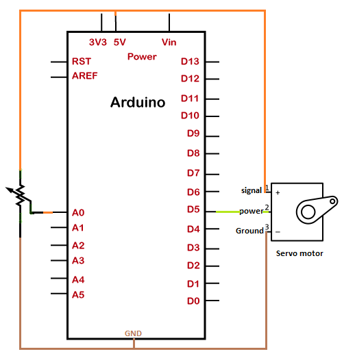
SketchConsider the below code: Steps to upload the code to the boardThe steps are listed below:
We can also modify the code to modify the performance of the servo motor accordingly. ConnectionThe steps to set up the connection are listed below:
Connection DiagramWe will show the connection using the Simulator so that the connections become clearer and more precise. We can make the same connection using the hardware devices. 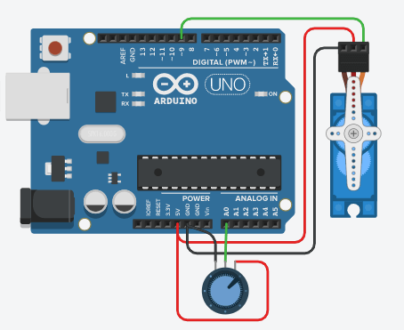
Output The shaft will rotate at angles between 0 and 180 degrees and again in the reverse direction. We can also modify the code by specifying it only in one direction from 0 to 180 degrees. Hence, we can make changes according to the requirements.
Next TopicArduino DC motor
|
 For Videos Join Our Youtube Channel: Join Now
Feedback
- Send your Feedback to [email protected]
Help Others, Please Share


