| |

Arduino buttonThe buttons are similar to switches that create and break electrical connections in the circuits. The button plays a transition between ON and OFF state. A single press turns the state ON, while another press turns the state OFF. It means that the button connects the two points in a circuit when we press them. There are two types of button, which are listed below:
We mostly use NO types of buttons. In such type, the state of the button is in rest. It means that a terminal in such a condition is not connected. It is shown below: 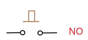
When we push the button, the terminals become electrically connected.
It is defined as the working state of the button. It connects the terminals of the circuit and allows current to flow through the load. It is shown below: 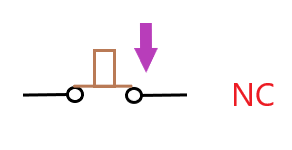
NC and NO are also defined as the momentary type of switches. Let's understand NO and NC with the help of a circuit. The NO state of a circuit is shown below: 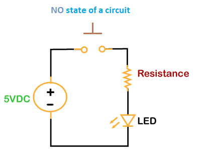
Due to the open ends of the circuit, the current cannot flow through it. The state of the circuit is in rest. The NC state of a circuit is shown below: 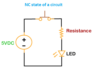
The current can easily flow through the circuit due to its connected ends. The LED will be ON until we push the button again. Another type of button is pushbutton, which is widely used in projects and circuits. Structure of pushbuttonLet's understand the structure of pushbutton. The pushbutton is a square shape button with four terminals, as shown below: 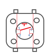
The two pins are next to each other on one side and another two pins on the other side. The pins across to each other are connected. The pins next to each other can only be connected, when we press the button. We can also connect two opposite terminals of the pushbutton, as shown below: 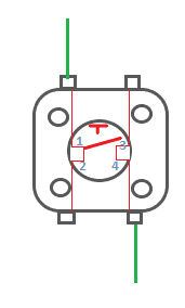
Let's understand buttons with an example. Code ExampleHere, we will light an LED by pressing the pushbutton. When we press the push button, it turns ON the LED connected to the PIN 13 on the Arduino UNO board. Components Required The required components are listed below:
The steps for such an example are listed below:
The circuit is shown below: 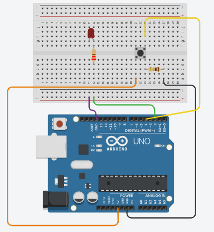
CodeThe code for the upper circuit is shown below: Output The LED will light be OFF at the initial state. When we continuously press the button, LED will light. The message 'LED is ON' will print on the Serial Monitor after every 500 milliseconds. Let's watch the output on the serial monitor. When LED is OFF, the output appears as: 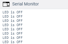
When LED is ON, the output appears as: 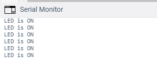
Next TopicArduino PWM
|
 For Videos Join Our Youtube Channel: Join Now
Feedback
- Send your Feedback to [email protected]
Help Others, Please Share


