| |

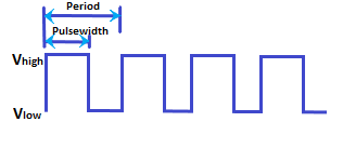
Arduino PWMThe PWM (Pulse Width Modulation) is a method of controlling the average voltage. It is a stream of voltage pulses that reduces the electric power supplied by the electrical signal. The effective voltage is controlled by the width of individual pulses in a stream of voltage pulses of a PWM signal. The common use of PWM pins includes controlling LEDs and DC Motors. The PWM in LED controls the frequency of the light. It means the LED will be ON/OFF at a frequency detectable by our eyes. The PWM in DC Motors acts like a pulse train of a DC signal. The DC motors receive a high or low electrical power input based on the width of the PWM pulses. We can also use PWM for voltage regulation, audio signal generation, devices control (pump, hydraulics, etc.), servo motor, etc. Principle of PWMThe state of the Digital Input/Output pins in Arduino is either HIGH ( 1 ) or LOW ( 0). Here, HIGH means the voltage is approx to 5V. LOW means the voltage is equivalent to 0 volts. The PWM is a square wave signal, which is represented as: 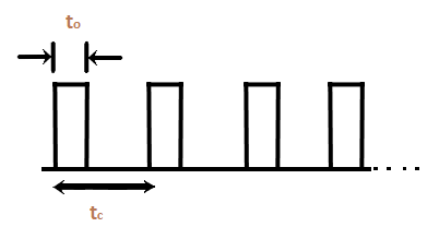
The duty cycle of the rectangular pulse is shown below: 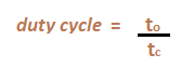
Here, to: It is the duration of the signal when the signal is HIGH. tc: It is the total duration of the signal as the sum of HIGH and LOW. Duty cycle of a PWM waveAs defined above, the duty cycle is the ratio of the pulse width to the total width of a signal. Consider the below image: 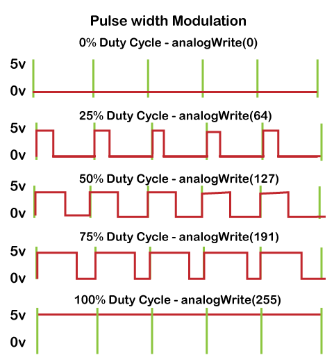
The above image displays the wave at different duty cycles. We can control the effective voltage of the DC motor in Arduino by regulating the PWM duty cycle. For example, Arduino UNOArduino UNO board consists of 14 digital Input/Output pins, where pin 11, 10, 9, 6, 5, and 3 are PWM pins. The pinMode(), digitalRead(), digitalWrite() functions control the operation of non-PWM pins. The pinMode() function is used to declare the specific pin as input/output. The digitalRead is used to read the HIGH or LOW state of a pin. We need to use the analogWrite() to set the duty cycle of a PWM (Pulse Width Modulation) pulse. Let's discuss analogWrite() in detail. analogWrite()It writes a PWM value or analog value to a pin. We can light an LED with varying brightness with the help of analogWrite(). It is also used to drive a motor at varying speeds. When an analogWrite() function is called, a stable rectangular wave of particular duty cycle is generated by the specified PWM pin until the next analogWrite() is called on that same pin. The PWM pins are present on every Arduino Board. The frequency can also vary for some PWM pins present on the particular board. For example, The PWM pins on the Arduino Leonardo/Micro are 3, 5, 6, 9, 10, 11, and 13. The frequency on pin 3 and 11 will be 980Hz, while other PWM pins have 490Hz of frequency. The syntax is: where, pin: Specified PWM pin on the board value: It determines the value of the duty cycle between 0 and 255. The data type used here is int. Note: The analogWrite( ) function is not related to the analogRead() or analog pins.What is the difference between analogRead() and analogWrite()?The main differences between analogRead() and analogWrite() are listed below:
Let's understand with an example. In the case of the PWM pin, we will specify the value instead of HIGH or LOW. For example, HIGH = 255 LOW = 0 Consider the below code: Here, the LED will light at full brightness. Let's discuss an example to control the brightness of the LED. How to calculate Arduino PWM?The analogWrite() function discussed above is used to generate a PWM signal in Arduino. The value associated with the analog signal is from 0 to 255. It means 256 levels of values. The maximum voltage read by the Arduino is 5V. We can determine the output PWM voltage by using the below formula:
PWM voltage = ( Duty cycle/ 256) x 5V
Code ExampleLet's discuss a method to control the brightness of an LED connected to the PWM pin. Here, we have connected the LED to the PWM pin 6. Consider the below code. In the above example, the brightness of the LED will decrease according to the specified value of brightness.
Next TopicArduino Library
|
 For Videos Join Our Youtube Channel: Join Now
Feedback
- Send your Feedback to [email protected]
Help Others, Please Share


