| |

Error DetectionWhen data is transmitted from one device to another device, the system does not guarantee whether the data received by the device is identical to the data transmitted by another device. An Error is a situation when the message received at the receiver end is not identical to the message transmitted. Types Of Errors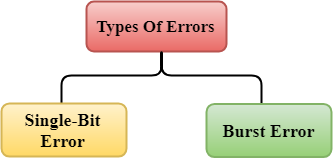
Errors can be classified into two categories:
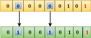
Single-Bit Error:The only one bit of a given data unit is changed from 1 to 0 or from 0 to 1. 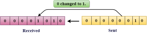
In the above figure, the message which is sent is corrupted as single-bit, i.e., 0 bit is changed to 1. Single-Bit Error does not appear more likely in Serial Data Transmission. For example, Sender sends the data at 10 Mbps, this means that the bit lasts only for 1 ?s and for a single-bit error to occurred, a noise must be more than 1 ?s. Single-Bit Error mainly occurs in Parallel Data Transmission. For example, if eight wires are used to send the eight bits of a byte, if one of the wire is noisy, then single-bit is corrupted per byte. Burst Error:The two or more bits are changed from 0 to 1 or from 1 to 0 is known as Burst Error. The Burst Error is determined from the first corrupted bit to the last corrupted bit. 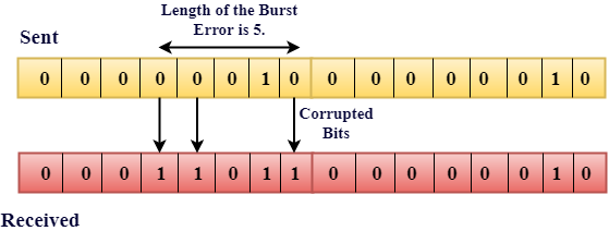
The duration of noise in Burst Error is more than the duration of noise in Single-Bit. Burst Errors are most likely to occurr in Serial Data Transmission. The number of affected bits depends on the duration of the noise and data rate. Error Detecting Techniques:The most popular Error Detecting Techniques are:
Single Parity Check
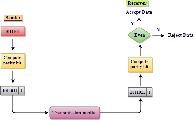
Drawbacks Of Single Parity Checking
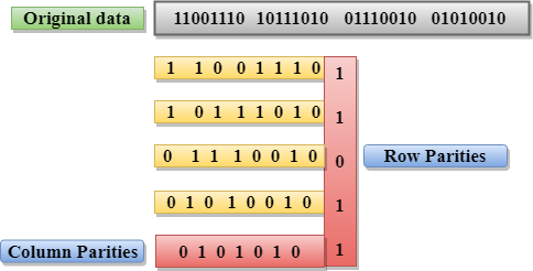
Two-Dimensional Parity Check
Drawbacks Of 2D Parity Check
ChecksumA Checksum is an error detection technique based on the concept of redundancy. It is divided into two parts: Checksum GeneratorA Checksum is generated at the sending side. Checksum generator subdivides the data into equal segments of n bits each, and all these segments are added together by using one's complement arithmetic. The sum is complemented and appended to the original data, known as checksum field. The extended data is transmitted across the network. Suppose L is the total sum of the data segments, then the checksum would be ?L 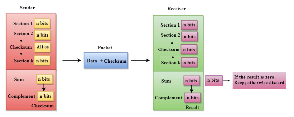
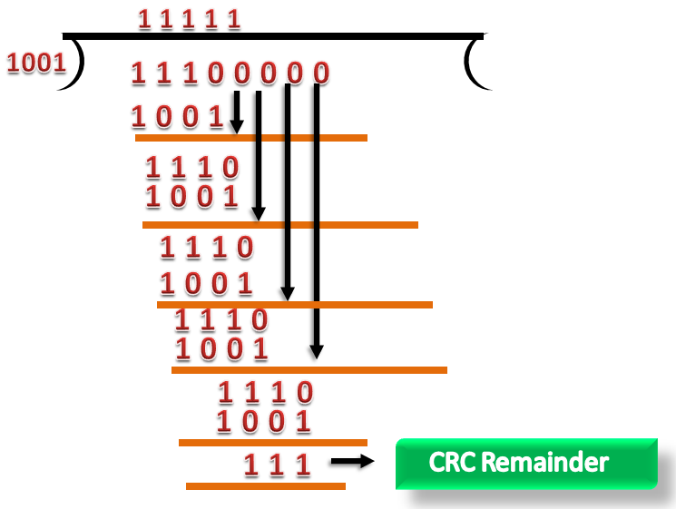
Checksum CheckerA Checksum is verified at the receiving side. The receiver subdivides the incoming data into equal segments of n bits each, and all these segments are added together, and then this sum is complemented. If the complement of the sum is zero, then the data is accepted otherwise data is rejected. Cyclic Redundancy Check (CRC)CRC is a redundancy error technique used to determine the error. Following are the steps used in CRC for error detection:
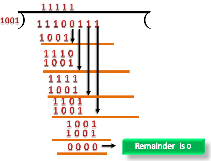
If the resultant of this division is zero which means that it has no error, and the data is accepted. If the resultant of this division is not zero which means that the data consists of an error. Therefore, the data is discarded. 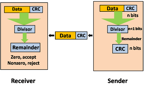
Let's understand this concept through an example: Suppose the original data is 11100 and divisor is 1001. CRC Generator
CRC Checker
Next Topic#
|
 For Videos Join Our Youtube Channel: Join Now
Feedback
- Send your Feedback to [email protected]
Help Others, Please Share


